Table of Contents
To do
- Warm:
- Assemble and test HV board
- Wire warm cable for Goldman thermometer
- Wire diverter board for Goldman thermometer. Can we use the source mover board?
- Check CDMSbats channel maps
Preparing S101
Detector arrived with many broken wirebonds at the DIBs.
-
- NOTE: if the surgery wasn't complete, we may have shorted two channels together: DIB3pA=Side1pF to DIB4pC=Side1pA. This will be difficult to verify until the detector is cold, I guess 4K - then there should be high interchannel resistances, since the Si will have high resistivity.
- 2021 October 8 measurements:
- The bad channels all have one connected wirebond, as indicated by interchannel checks
- DIB4pC wasn't open originally but is now
- DIB1pB is reading much lower than originally. Is it possible that wirebonds are touching?
- I doubt that this is a problem. Cross-channel resistances on the same DIB are all around 1.2 kΩ, to the other side around 2.0 kΩ. And note that both pB channels have very similar resistances. This suggests that the older, higher resistance reading is spurious.
| S104 Detector Electrical Checkout | ||||||
|---|---|---|---|---|---|---|
| DIB chan | Det chan | 2021-07-02 [Ω] | 2021-07-28 | 2021-10-07 | 2021-10-08 | 2021-10-11 |
| DIB1pA | Side1pD | OL | repaired | 314 | ||
| DIB1pB | Side1pB | 929 | 84 | |||
| DIB1pC | Side2pE | OL | OL (pin2 connected) | repaired | ||
| DIB1pD | Side2pD | OL | OL (pin2 connected) | repaired | ||
| DIB1Q | Side1pE | 278 | 278 | |||
| DIB3pA | Side1pF | OL | repaired | 442 | ||
| DIB3pB | Side2pF | 452.3 | 452 | |||
| DIB3pC | Side2pC | 314.6 | 315 | |||
| DIB3pD | Side2pB | 83.1 | 83 | |||
| DIB3Q | Side1pC | 374 | 376 | |||
| DIB4pA | nc | - | ||||
| DIB4pB | nc | - | ||||
| DIB4pC | Side1pA | 45 | OL (pin2 connected) | |||
| DIB4pD | Side2pA | OL | OL (pin1 connected) | repaired | ||
| DIB4Q | nc | - | ||||
Preparing HV board
Need to replace resistors that were removed for Run70 for G101d. Now we want to connect all Side2 channels to bias, so need resistors for all 6 Side2 TESs.
- 2021 Oct 20: Resistor replacement finished
- HV board page has been updated.
Can we also set up the second board that biases Side1? That way we could swap between them on this run, test both sides.
Preparing phonon channel twisted pairs
The plan for this run is to use no side coaxes - instead we'll have twisted pairs from DIB to Tower for each phonon channel. We should be able to wire all 12 phonon channels.
Since two of the DIBs connect 5 phonon channels each, we need at least some channels to cross from one tower face to another.
We can reroute channels so that they match the Run68 et al scheme, which will simplify processing - we won't need a new channel map.
| Run 68 Wiring Scheme for S101 (which no longer exists) | ||||
|---|---|---|---|---|
| pA | pB | pC | pD | |
| DIB1 | SIDE1pE | SIDE1pB | SIDE1pD | side2pE(-side2pD) |
| DIB3 | side2pB(d4) | side2pA | SIDE1pA | n/c |
| DIB4 | side2pC | side2pF | SIDE1pC | SIDE1pF |
| CAPITAL = Side 1, lowercase = Side 2 “-” indicates a non-readout channel shorted to a readout channel for biasing purposes |
||||
The plan:
- Use Belden 8079 Magnet Wire. 8.5“ is probably long enough
- MillMax pins on the DIB side. May want to cut them shorter so they don't stick out too far
- Strip connectors on Tower side. For two of them I cut 8-pin MillMax(?) connectors. We should buy more of these. For one we can reused the copper adapter plate we used last time for twisted-pair connections.
- This will produce reusable connectors. Tower channels can be routed to any DIB channels.
| Twisted pair phonon channel connector used in Runs 72&73 | Parts for new connectors. The MillMax pins extend 10 mm past the socket - we're cutting that down to 4 or 5 mm. |
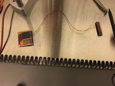 | 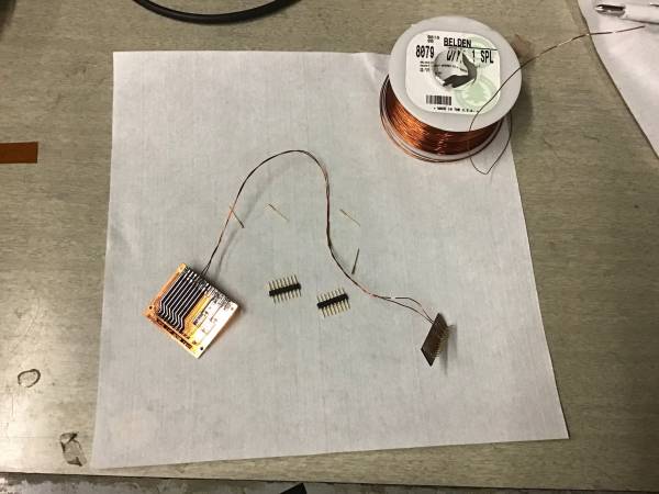 |
| One twisted pair soldered on, 8.5” | Fit test on tower. Should be able to extend to a Position 2 detector and 2-tower-face offset. |
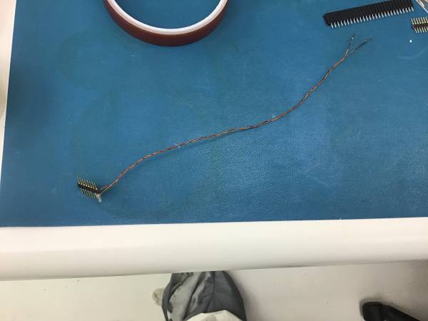 | 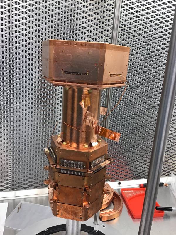 |
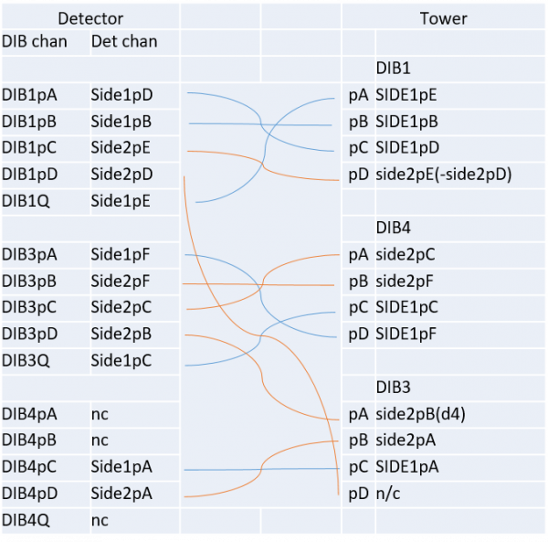 |
| Note: in the final column the channel labels refer to the old S101, not the new S104. S101 had some Side2 channels not connected for readout; S104 has all channels connected for readout. |
|---|
LEDs
Since we're not using side coaxes we'll also need wires from detector to tower for the LEDs.
Preparing thermometry
The Tower thermometer seems to be no longer trustworthy below 0.5 K. We have borrowed (permanently?) a thermometer from the Goldman lab. We should figure out how to mount it on the Tower somehow. We should also decide if we want both the Goldman thermometer and the Tower thermometer. If we want both we'll need more wires. We could reroute some stripline wires for this purpose.
Goldman thermometer calibration
| Goldman thermometer | |
|---|---|
 |  |
Size and mounting
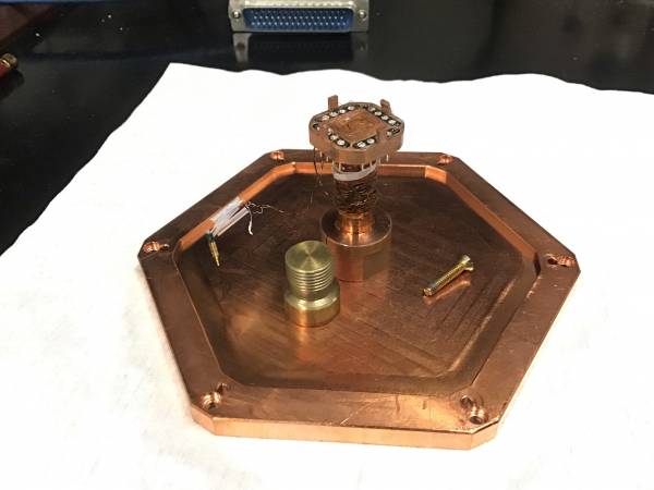
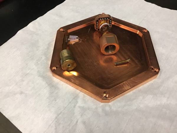
The Goldman thermometer is pretty much permanently attached to a copper test stage. The bottom of the stage is a large threaded hole into which a large brass bolt (of sorts) is inserted. The bottom of the brass bolt has a threaded hole. There's also an aluminum base plate that the brass nut can be screwed onto.
| Test stage height | 4.51 cm |
|---|---|
| Test stage plus brass nut height | 5.48 cm |
The plan is to attach the thermometer to the lid that will be at the top of the stack. We can drill a hole in the middle of the lid. We could either drill a large hole for the brass nut (then the bottom of the nut would occupy some space in the housing), or we could drill a small hole for the screw (then the full test-stage-plus-brass-bolt would sit on top of the lid). Either way it should fit without touching the ceiling of the 30mK can - according to my spreadsheet on the fridge dimensions, with a 2-housing stack there should be a full 6.05 cm clearance. So - we'll probably drill a hole for the small screw.
- 2020 October 15: Drilled a hole for the brass base nut to attach to a housing lid
Wiring
The nominal plan is to connect the Tower thermometer in the ordinary way, using the plug in the fridge wiring. Then the Goldman thermometer would be connected to stripline wires as an additional accessory, with the SQUET/stripline interposer board and the DSub/HVbox diverter board adjusted accordingly. We'd then need a connector to the LakeShore bridge to read out the thermometer.
-
- cut the Tower thermometer wires down to about 1/3 their original length, and soldered a new connector (female 2.54mm pitch)
- removed 0.06“-pitch male connector from Goldman thermometer, replaced with female 2.54mm pitch connector
- prepared four 28 AWG wires, 11.5” long with mill-max pins on each end to wire Goldman thermometer. One end plugs into thermometer connector, the other into the proper Tower socket.
Goldman wire room temperature resistance: 2.0 kΩ
Accessory wiring
For source mover - can probably repeat from the last run (don't need electrode wire this time). Maybe include extra thermometer wiring.
2021 January 7: info on Run74 accessory wiring.
- 2021 October 15: Replaced two pins on SQUET/Stripline interposer. This now has enough connections to wire source mover coils, endstops, and four wires from Goldman thermometer.
- 2021 October 25: Discovered Face4 pin13 on Tower has short to chassis. Remap thermometer wires to avoid this pin.
- New map shown below; old map had the purple/purple/black/black plug from the interposer spanning Pins 9-13, now it's 11-15.
| Run 75 accessory wiring | ||||||||||||||||
|---|---|---|---|---|---|---|---|---|---|---|---|---|---|---|---|---|
| accessory | coil1 | coil1 | coil2 | coil2 | therm+ | near end | far end | therm+ | therm- | therm- | ||||||
| acc wire | kap | kap | kap | kap | gold | blu | w blu | nc | gold | gold | gold | |||||
| Tower F4 | 1 | 2 | 3 | 4 | 5 | 6 | 7 | 8 | 9 | 10 | 11 | 12 | 13 | 14 | 15 | 16 |
| interposer conns | brn | w brn | org | w org | blu | w blu | grn | pur | pur | blk | blk | |||||
| no soc | no soc | no soc | no soc | no soc | no soc | no soc | no soc | no soc | no soc | |||||||
| stripline | 49 | 50 | 8 | 9 | 11 | 12 | 13 | 2 | 46 | 45 | ||||||
| label | pBr3 | pBr4 | pCr3 | pCr4 | pAr3 | pAr4 | pAr5 | pAr1 | pDr4 | pDr3 | ||||||
| STRIPLINE 48 | ||||||||||||||||
| CABLE 1 | ||||||||||||||||
| stripline D50 | 36 | 18 | 8 | 23 | 4 | 19 | 1 | 17 | 40 | 41 | ||||||
| DCRC/diverter Dsub | 48 | 33 | 10 | 28 | 14 | 32 | 17 | 1 | 44 | 43 | ||||||
| Dsub diverter board | U09-2 | U10-3 | U06-3 | U07-3 | U08-4 | U09-1 | U10-4 | U01-4 | U07-5 | U06-4 | ||||||
| Warm-side Accessory Wires: Motor coil (MC), endstop (ES), Goldman thermometer (GT) | ||||||||||||||||
| diverter board wires | MC Orange | MC Brown | MC Red | MC Yellow | GT Black | ES White Blue | ES Green | GT Green | GT Red | GT White | ||||||
- For the Dsub diverter board, use “DCRC/diverter Dsub” above to wire accessories (Goldman thermometer) to the cable-side pins, and use “Dsub diverter board” dip-switch labels to disconnect these lines from the DCRC.
- 2021 November 2: solder Dsub connector to cable for Goldman thermometer (this will plug into the LakeShore bridge cable). Wiring diagram below:
- Also useful: in the endstop cable (blue, leading to BOB extension), connect the Blue wire to the diverter board ground plane. Then it will be easier to measure endstop-to-ground resistance, right at the BOB extension.
| Cable for Goldman thermometer - warm diverter board to LakeShore bridge cable | ||
|---|---|---|
| Connection | Dsub pin # | Wire color |
| V+ | 5 | Black |
| V- | 14 | Red |
| I+ | 10 | Green |
| I- | 11 | White |
Tower faces
Tower 1 has two adjacent faces, 1 and 6, that have problems with phonon channel wires. With the twisted pairs we have a choice for which faces to use so probably we'll use one face that's offset from its DIB.
Face 6 could be used for the accessories. It has one bad socket at Pin 5, we'd have to avoid that. The 4-pin interposer plug would plug into 1-4, the 7-pin one could plug into 5-11.
Tower plan:
- Align DIB1 with Face5. This aligns DIB3/DIB4 with Face3/Face1.
- SQUETS 1,2,3 will be on Faces 5,3,2.
- Thus most DIB1&DIB3 channels will connect on the same face as the DIB. DIB4 channels will connect one face over.
- Accessories will plug into Face4.
- Accessory interposer at Face3/SQUET 2
- We'll try orienting Face 5/3/2 → SW/W/E → Striplines 43/48/41
- actually we wound up not doing this, Face 3 is W. So it's Face 5/3/2/(4) → SE/W/NW/(SW)
| Run 75 Tower Wiring Diagram | ||
|---|---|---|
| Align DIB1 with Face5 | ||
| Tower | DIB | Label |
| Face5pA | DIB1Q | Side1pE |
| Face5pB | DIB1pB | Side1pB |
| Face5pC | DIB1pA | Side1pD |
| Face5pD | DIB1pC | Side2pE |
| Face5LEDs | DIB1LEDs | |
| Face3pA | DIB3pC | Side2pC |
| Face3pB | DIB3pB | Side2pF |
| Face3pC | DIB3Q | Side1pC |
| Face3pD | DIB3pA | Side1pF |
| Face2pA | DIB3pD | Side2pB |
| Face2pB | DIB4pD | Side2pA |
| Face2pC | DIB4pC | Side1pA |
| Face2pD | DIB1pD | Side2pD |
| Face4-1 | coil1 | |
| Face4-2 | coil1 | |
| Face4-3 | coil2 | |
| Face4-4 | coil2 | |
| Face4-5 | therm+ | |
| Face4-6 | near endstop (blue) | |
| Face4-7 | far endstop (white-blue) | |
| Face4-12 | therm+ | |
| Face4-14 | therm- | |
| Face4-15 | therm- | |
SQUETs
Since this is an HV detector we will want to use SQUET channels with reduced shunt resistances, as in all HV runs since Run 66. But in recent runs we've used SQUETs with only the Side1 channels functional and modified. In this run we have the opportunity to read out all 12 channels, but this will only be possible with three SQUETs with all channels working.
We have been conservative with SQUET modifications. In particular we have left three SQUETs each with 4 good channels unmodified - these are used to run 4-inch iZIPs. We probably don't want reduced shunts for the iZIPs - this would presumably require higher QET biases.
Actually I'm not sure this is a real concern. In Run 71 (most recent iZIP run G106a) the highest QET bias used was 140 uA; 3x that would be 420 uA which is no problem. Not sure what Rnormal is for G106a but for G133 (iZIP pathfinder) it was 85-90 mOhm, actually less even than the HV prototypes (G101: 90-150 mOhm, S101: 75-90 mOhm). Contrast with CDMS2, where the phonon channel Rn in the ZIPs was 1200 mOhm! And SuperCDMS Soudan 3-inch iZIPs had Rn of 500-700 mOhm. So - maybe reduced shunts are better for all 4-inch detectors.
We would like to avoid multiple modifications of the same SQUET channel, because the bond pads will become unusable (particularly because we have a standard of double-bonding, which should cut the parasitic resistance in half, and we know this is a major noise component because the SQUIDs probably don't get cold enough for the bonds to superconduct). But if we're OK with reduced shunts on all our SQUETs this shouldn't be a problem.
The table below has info copied from the cold hardware page.
| SQUET | results | modifications | use | 4 good chans? | mods needed |
|---|---|---|---|---|---|
| ZC-13 | problems with Qo gate to source ← no problem seen 2019-09-13 | pB, pC, pD shunts reduced to 6.7 mΩ. pB TES lines shorted. | yes | pA, pB | |
| ZC-74 | All good, except for several bad connections of S/L pins at the middle layer. Using jumper wires to reconnect these. See diagram below. | none | iZIP | yes | pA, pB, pC, pD |
| ZC-39 | looks good | none | iZIP | yes | pA, pB, pC, pD |
| ZC-70 | FET TSense reads high. Otherwise all good. | none | iZIP | yes | pA, pB, pC, pD |
| ZC-26 | problems with Qi gate to source, gate to drain (both open) ← no problem seen 2019-09-13. Feedback A resistance too low (1 kOhm). | pC, pD shunts reduced to 6.7 mΩ. | maybe | pA, pB | |
| ZC-31 | looks ok at RT. But we may have damaged SQUIDs during Run 66. | pC, pD shunts reduced to 6.7 mΩ. pB shunt reduced to 0 mΩ (3-bond) | maybe (damaged SQUIDs?) | pA, pB | |
| ZC-68 | SQUID D open, Feedback D open. pB has odd SQUID behavior (R66, R68) at high QET bias | pA, pB, pC shunts reduced to 6.7 mΩ. pD shunt reduced to 0 mΩ (1-bond) | HV | no | - |
| ZC-23 | SQUID A reads open. Feedback B too low. Input coil C too high. | pA, pB, pC, pD shunts reduced to 6.7 mΩ | no | - | |
| ZC-24 | Input coil A open, SQUID A open, Feedback A too high. SQUID C behaves badly (R69) | pC, pD shunts reduced to 6.7 mΩ. | no | - |
- 2021 Nov 26: modified ZC-13, reduced pA shunt (now all are reduced) and removed shorting wires on pB.
Checkout shows pC feedback open. This was working in Run73.Room temperature electrical checkout OK.
- Is ZC-26 usable? Feedback A resistance is too low - and in Run 66 this channel showed “weak pulses”. Although the TES was also shorted to chassis, so not sure what the real problem was.
- 2021 Nov 28: modified ZC-39, reduced all four phonon channel shunts to 6.7 mΩ.
- 2021 Nov 29: modified ZC-70, reduced all four phonon channel shunts to 6.7 mΩ.