−Table of Contents
k100 cold hardware
Design documentation of cold hardware: http://titus.stanford.edu/cdms_restricted/coldhardware/html/coldhardware.html
Tower
| Tower 1? (Old tower) | MF update 2021/10/25 |
|---|---|
| Face | Bad Lines |
| 1 | 5-10 (PC-LEDs) Coax wires are simply absent… |
| 2 | None |
| 3 | None |
| 4 | Pin 13 (qO Feedback) short to chassis |
| 5 | None |
| 6 | 5 (PC ret) Broken socket on 4K side |
Side Coax
| Name | Type | Length (Pin-pin) | Status |
|---|---|---|---|
| ZB1-1-11 | CDMS2 p1 | 4.665 | Good |
| ZB1-1-9 | CDMS2 p1 | 4.666 | Good |
| ZB1-6 | CDMS2 p1 | 4.656 | No phonons |
| ZB3-1 | CDMS2 p3 | 5.602 | ? |
| ZB1-4-6 | CDMS2 p4 | 6.058 | Good phonons, Bad qI Cc? |
| ZB1-4-8 | CDMS2 p4 | 6.058 | Good |
| ZB4-4 | CDMS2 p4 | 6.063 | Good phonons, Bad qI Cc? |
| ZB-5-1 | CDMS2 p5 | 6.5 | ? |
| ST-3-10 | sCDMS short | Good | |
| ST-3-3 | sCDMS short | Good | |
| ST-3-8 | sCDMS short | 4.525 | Good |
| ST-3-9 | sCDMS short | qO Rb, qO Rf, qI Rb all open, qO Cc short. DIB-side Pin1 shorts to chassis if pushed and also can short if cooled to 77K. | |
| ST-4-10 | sCDMS medium | 5.617 | ? |
| ST-4-9 | sCDMS medium | 5.617 | ? |
| ST-5-10 | sCDMS long | 6.7 | ? |
| ST-5-11 | sCDMS long | 6.702 | ? |
SQUET
SQUET wiring checks:
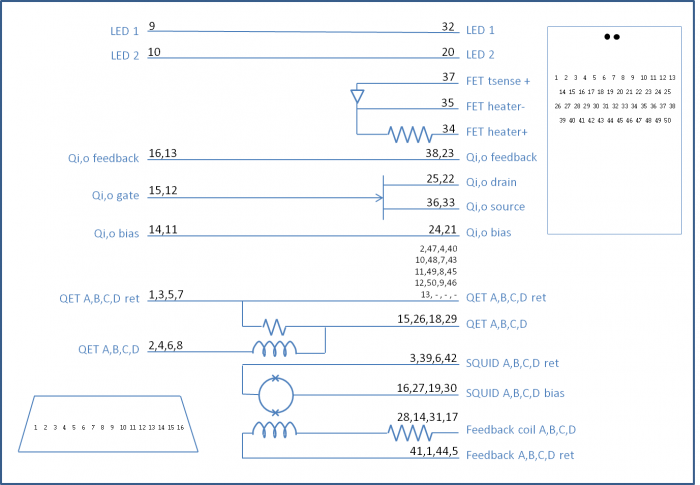
The things to check for a SQUET's wiring are whether there is continuity where there should be, whether the various components show the right resistances, whether the wiring is “standard” or “flipped”, and whether there are shorts.
- Standard wiring is as indicated in the diagram
- In Flipped wiring, the QET and QET return pins are flipped on the Tower side (12-pin connector)
- The QET pins on the Tower (12-pin) side should show the large room-temperature input coil resistance when measuring to any of the other three QET pins
These are standard room-temperature values of various components:
- Continuous lines: less than a few Ω
- FET TSense diode: when measured forward, ~500 kΩ
- FET heater resistor: ~ 1 kΩ
- FET gate-to-drain or gate-to-source: ~500 kΩ
- QET shunt resistance: about 20/13 Ω if shunt resistance is 20/6.7 mΩ (these are apparently room-temperature wirebond resistances)
- QET input coil resistance: ~14 kΩ
- SQUID bias-return resistance: ~4 kΩ
- Feedback resistor+coil: ~20 kΩ
Here are notes on how to modify shunt resistances on SQUETs: hv2rewiring
| SQUET | date tested | wiring type | results | name | modifications |
|---|---|---|---|---|---|
| ZC-68 | 2019-04-19 | standard | SQUID D open, Feedback D open. pB has odd SQUID behavior (R66, R68) at high QET bias | MF | pA, pB, pC shunts reduced to 6.7 mΩ. pD shunt reduced to 0 mΩ (1-bond) |
| ZC-74 | 2019-09-04 | standard | All good, except for several bad connections of S/L pins at the middle layer. Using jumper wires to reconnect these. See diagram below. | MF | pA, pB, pC, pD shunts reduced to 6.7 mΩ. |
| ZC-23 | 2019-04-19 | flipped | SQUID A reads open. Feedback B too low. Input coil C too high. | MF | pA, pB, pC, pD shunts reduced to 6.7 mΩ |
| ZC-31 | 2018-04-06 | standard | looks ok at RT. But we may have damaged SQUIDs during Run 66. | MF | pA, pB, pC, pD shunts reduced to 6.7 mΩ. |
| ZC-24 | 2019-04-19 | flipped | Input coil A open, SQUID A open, Feedback A too high. SQUID C behaves badly (R69) | MF | pC, pD shunts reduced to 6.7 mΩ. |
| ZC-26 | 2019-04-22 | flipped | | MF | pA, pB, pC, pD shunts reduced to 6.7 mΩ. |
| ZC-39 | 2018-11-16 | standard | SQUID C&D both open (Run 76) | GR | pA, pB, pC, pD shunts reduced to 6.7 mΩ. |
| ZC-13 | 2019-04-22 | flipped | | MF | pA, pB, pC, pD shunts reduced to 6.7 mΩ. |
| ZC-70 | 2019-09-04 | standard | FET TSense reads high. SQUID A open (Run 76) | MF | pA, pB, pC, pD shunts reduced to 6.7 mΩ. |
notes:
- “ZC-37” is sometimes referred to in the wiki but I think this is ZC-39 (it's a little hard to read the label)
- “ZC-87” was referred to in Run 60 but this doesn't seem to exist. Maybe this is also ZC-39??
- “ZC-28” is referred to in the old days, going back to Run 35, but no longer seems to exist
- Update: CDMS elog indicates Hassan sent this to UCB in Mar 2013
- “ZC-15” is also in old runs, but was sent to UCB in Nov 2010 according to the elog.
- On 2016 Apr 13 we got 6 SQUETs from Soudan: ZC-14,ZC-24,ZC-26,ZC-31,ZC-39,ZC-68. All accounted for in the above table except ZC-14, don't know what happened to that one.
- Update: “ZC-14” is probably actually ZC-74
- italics indicate a SQUID chip problem that is verified on the SQUID card itself. So presumably not a connection problem (wirebonds all look OK by eye).
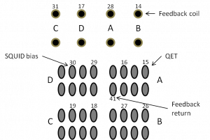
- ZC-74 jumper diagram below, for all S/L pins that connect at the middle layer. This is the view from the back of the FET card. Numbers refer to corresponding S/L pins. For example photo see 2019 Oct 25 run diary.
Stripline
| Stripline | Condition | Location | Notes |
|---|---|---|---|
| 19 | Many breaks | | - |
| 20 | Some breaks | | - |
| 27 | Some breaks | | - |
| 37 | No breaks (1/2018) | | ~9.5 ft |
| 41 | No breaks (1/2018) | | ~9.5 ft |
| 43 | No breaks (1/2018) | | |
| 48 | No breaks (1/2018) | Clean Room | |
| 61 | Clean Room | ||
| 66 | Clean Room | ||
| L1 | No breaks (1/2018) | Clean Room | White G10? material @ warm end, narrow, flexible stripline material, ~9.5 ft |
| L4 | No breaks (1/2018) | Clean Room | White G10? material @ warm end, narrow, flexible stripline material, ~9.5 ft |
Pin map
1K pot pin map