2019/04/03 (Wednesday)
| Setup | DIB1/3/4 → 3.2 MHz filters 2/3/1 → cable 3/1/2 → gender changer 3/?/2 → HVConn 1/3/2 → HV 1/2 → DCRCX(4)/DCRC50(3) DCRC33(2) → 1kV power supply → HV input Lead poly shield is erected, N/E/W walls complete, no poly or lead on S wall. |
|---|---|
| 0920 | Tower/MC/Coldplate = 40.5/29.8/183 mK, Still = 1.71±0.15 K / 0.150 mbar, G1/G2 = 287/261 mbar, 1K Pot = 1.77 K / 13 mbar. MB = 39.4% |
| 0930 | Chad replaced the cdms2 boot disk and rebuilt cdms2 yesterday. Let's try to start up the DAQ again. |
ssh to cdms2, get a warning that the RSA host key has changed, but this is probably fine. Following the procedure to start MIDAS(cdms:k100:procedure:midas), sourced midasUMN.env and tried to run ./start_daq_umn.sh. Got the following:
cdms2:bin cdmssoft$./start_daq_umn.sh
Good, we are on cdms2!
mhttpd: error while loading shared libraries: libodbc.so.2: cannot open shared object file: No such file or directory
mserver started interactively
Becoming a daemon...
mlogger: error while loading shared libraries: libodbc.so.2: cannot open shared object file: No such file or directory
Becoming a daemon...
So mserver and lazylogger were able to start, but mhttpd and mlogger need libodbc.so.2
| 1045 | Turns out we needed to install unixODBC, which Chad just did. Now the DAQ programs start as usual. |
|---|---|
| 1045 | Fill LN2 cold trap full. |
| 1145 | Iterating with Chad and Anthony to get vnc working properly on cdms2. For now, just use run the SQUIDtuningGUI on jiajin. |
| 1150 | Start up dcrc programs, can see nice pulses on all DCRC4 channels. DCRC3 pC has weird, jagged noise. DCRC3 pD has no pulses and large noise spikes below baseline. |
| 1155 | Zap DCRC3 SQUIDs. Takes 5 tries for this to work without the “problem in toolstimeout” error. So restarting cdms2 didn't fix that issue. |
| 1200 | Zap DCRC3 SQUIDs again. This time it works right away. |
| 1220 | DCRC3 channels look as before. DCRC3 pC is showing distorted, inverted pulses and jagged noise. DCRC3 pD has more usual noise, but spikey, negative pulses/noise excursions. |
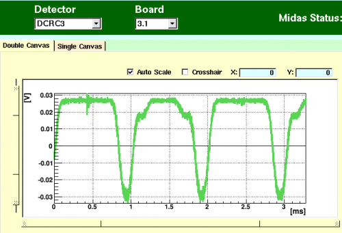
| 1224 | Let's check out these SQUIDs. Set DCRC3 pC QET bias = 0. Set DCRC3 pC to open loop. Apply test signal 400 mVpp test signal to pC FB lines, can see it with ADC connected to FB. When I switch over to looking at the preAmp, the modulation curve looks gross. Do the same on DCRC3 pD, it looks more reasonable. |
| DCRC3 pC modulation curve | DCRC3 pD modulation curve |
|---|---|
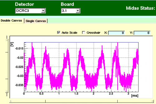 |  |
| 1250 | Am unable to get a nice modulation curve on DCRC3 pC. This SQUET might be slowly dying. Maybe the HV is breaking it down somehow? |
|---|---|
| 1253 | Adjust DCRC3 pD SQUID settings to SQUID bias/lockpoint = -65/-2.5 Why should these be so different? It is a weird coincidence that these are the same settings we had been using for DCRC3 pC previously. |
| New DCRC3 pD modulation curve |
|---|
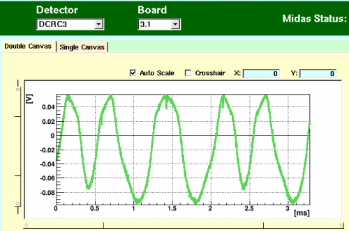 |
| 1300 | Pulses look better on DCRC3 pD now. |
|---|---|
| 1340 | Commence LHe transfer, MB = 32.9% |
| 1358 | Trying to improve DCRC3 pC modulation curve. Try pushing the detector cables into the HV board harder to make sure they're seated, do the same to the DCRCs themselves. This improves the modulation curve. [image not archived: neutral.svg] Something may have just come unseated. Push the cables at the ebox end too. |
| 1400 | Zap DCRC3 SQUIDs a couple times. |
| 1415 | Cease LHe transfer, MB = 91.5% |
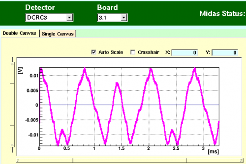
| 1505 | Adjust DCRC3 pC SQUID settings to SQUID bias/lockpoint = -80/-5.3 Here is the best modulation curve I could get, it's still not pretty. Also had to reduce DCRC3pC FE gain. |
|---|
| New DCRC3 pC modulation curve |
|---|
 |
| Current best settings are below |
DCRC4
VGAGain (multiplicative factor)
[0] 2
[1] 2
[2] 3
[3] 1
LockpointAdjust (mV)
[0] -3.6
[1] -3.8
[2] -3.7
[3] -2.5
SQUIDBias (uA)
[0] -85
[1] -70
[2] -85
[3] -90
QETBias (uA)
[0] 440
[1] 380
[2] 430
[3] 0
DCRC3
VGAGain (multiplicative factor)
[0] 1
[1] 5
[2] 2
[3] 5
LockpointAdjust (mV)
[0] -4
[1] -4
[2] -5.3
[3] -2.5
SQUIDBias (uA)
[0] -80
[1] -85
[2] -80
[3] -65
QETBias (uA)
[0] 0
[1] 500
[2] 460
[3] 410
^ 1515 | Try triggering on DCRC4 channels. DCRC3 pulses seem uncorrelated with DCRC4 triggers. We may have lost the timing link. Stop and restart DCRC programs. Now the pulses are synchronized across DCRCs. |
| 1527 | Start 30 min background series at HV = 0V CDMS detector: Driver Gains = 1x, DCRC4/3 QET biases = (440/380/430)/(500/460/410) uA, Front-End Gains = (2/2/3)/(5/2/5) 1000 BOR randoms, trigger on |
|---|---|
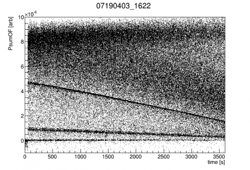
| 1614 | Alright let's try to take some HV data like this. We are interested in understanding HV noise as a function of bias. One way to do that is to apply a constant HV bias and let the counter bias accumulate to slowly reduce the effective crystal bias and effectively scan down to 0 V. |
| 1615 | Start a 60 min background series at HV = 300V with 1 minute 15% prebias CDMS detector: Driver Gains = 1x, DCRC4/3 QET biases = (440/380/430)/(500/460/410) uA, Front-End Gains = (2/2/3)/(5/2/5) 1000 BOR randoms, trigger on use sequence HVconst_300V_prebias_15_1_dur_60min_flash.msl |
| 1615 | The bias started turning up at 16:15:15 |
| 1617 | Leakage peaks at Vtest = 28 mV around HV = 100 V |
| 1621 | Prebias begins at HV/Vtest = 343.9 V/20 mV |
| 162247 | Ramp-down ends and data taking commences with HV/Vtest = 299.1 V/4.95 mV |
| 1708 | Bias has been steady at HV/Vtest = 399.1 V/3.40 mV |
| 1710 | Fill LN2 cold trap full. |
| 1735 | Flash only heated fridge to 41.5 mK. May want to flash again before more data taking. |
| 1736 | Change HV to negative polarity. |
| 2019 | Flash detector for 30s using flashandflash tool, tower rises to 41.7 mK before cooling. |
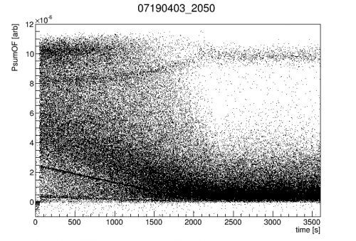
| 2042 | Start a 60 min background series at HV = -300V with 1 minute 15% prebias CDMS detector: Driver Gains = 1x, DCRC4/3 QET biases = (440/380/430)/(500/460/410) uA, Front-End Gains = (2/2/3)/(5/2/5) 1000 BOR randoms, trigger on use sequence HVconst_300V_prebias_15_1_dur_60min_flash.msl |
| 2045 | Vleak peaks at -35 mV. Running remotely so not able to measure HV. |
Quick results of these +/-300V runs. The positive bias started with a higher amplification and lasted longer, though the 60keV lines have similar slopes. The leakages were similar, so the bias magnitude applied to the electrode should be similar. Odd.
| +300V | -300V |
|---|---|
 |  |