2019/10/25 (Friday)
| Status: Installing tower for 2nd attempt at Run 71 cooldown. | |
| 1000 | Investigating ZC-74 on the bench. Feedback C is clearly bad. Pin 31 (Feedback Coil C) connection to SQUID-card pin (on back of SQUET this is upper-left pin on lower-left quadrant) is bad. |
| 1015 | Reseating Pin 31 after loosening it with soldering iron seems to fix the connection |
| 1025 | Plug ZC-74 back into stripline. (Don't bother to plug into tower yet.) Check at breakout box. Various SQUID and FB connections are bad. Many of them are OK after you squeeze the SQUET a bit. The worst is Feedback B. Intermittently bad are SQUID A&C and Feedback A. |
| 1125 | Channels that look fine and stable on the bench can look bad when plugged in, depending on how tightly plugged in it is. Let's try plugging into an old stripline on the bench, to replicate the tensions on the pins that occur when it's plugged in. |
| 1135 | With ZC-74 plugged into an old stripline on the bench, check all 4 SQUID and Feedback resistances from the pins on the back of the SQUET. All look OK. weird. |
| 1145 | Try plugging into fridge stripline again. Now most of them are OK, both checking on the pins on the SQUET and at the breakout box. The one exception is Feedback C. This is the one I messed with on the bench, reseating Pin 31 (which is now somewhat too short). Back to the bench, we'll look at that connection again. |
| 1200 | Adjust seating of Pin 31 again. Plug ZC-74 back into fridge stripline. Notice that with some channels, if I flip the Fluke 87 meter's scale or switch back and forth, the channels read OK again. All look OK except again Feedback C. Let's just make a jumper wire for Pin 31. |
| 1225 | Attach a jumper wire on the back of SQUET ZC-74 from Pin 31 to Feedback Coil C pin leading to SQUID card. 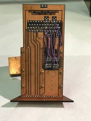 |
| 1225 | Plug ZC-74 back into Stripline 48. All four SQUIDs and Feedback connections look OK at BOB. But note: need to switch meter switch back and forth on some of these to get a good reading |
| 1306 | Install ZC-74 and remaining 4K heatsinking. Put screws in unused SQUET and SQUID board mounting holes. Tape over exposed gap on face with motor wiring harness. |
| 1316 | Quick electrical check of all 3 DIBs looks fine. As above, setting the Fluke 87 resistance range manually fixes some strange measurements. |
| 1415 | Put indium o-ring on bottom IVC piece and install it (screws not tightened yet). The stripline to DIB 2 (S/L 48, the longest) was kind of in the way. We put an additional curve in it and taped it to a heat sink to make it fit. 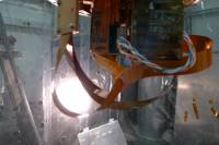  |
| 1425 | Electrical checkout - everything looks OK! |
| 1450 | IVC screws mostly tight. Start pumping out IVC slowly with scroll pump. |
| 1500 | Scroll pump on IVC = 0.16 mbar |
| 1510 | Scroll pump on IVC = 0.1 mbar. Switch to pumping IVC with turbo pump. |
| 1515 | Turbo pump on IVC = 4.6 μbar |
| 1555 | Turbo pump on IVC = 1.4 μbar |
| 1650 | Turbo pump on IVC = 1.0 μbar |
| 1510 | Start cryocleaning mixture through LN2 Cold Trap 1, V6 = 12.6% G2 pressure goes too high, hits 982 mbar. Having trouble getting this right…. |
|---|---|
| 1515 | Start cryocleaning mixture through LN2 Cold Trap 1, V6 = 12.5% |
| 1520 | Increase V6 → 12.6% to speed up flow |
| 1535 | Increase V6 → 12.7% to speed up flow |
| 1555 | Increase V6 → 12.8% to speed up flow |
| 1615 | Stop cleaning through Trap 1 after 60 min. G2 flow pressure was 565-705 mbar. Pump mixture to dump. Removed 7.1 mbar. |
Realize later that the jumper wire fix on SQUET ZC-74 was done wrong. I connected the Feedback C line in such a way that it shorts out the feedback resistor and connects directly to the coil. The yellow arrow below shows where it should be connected: 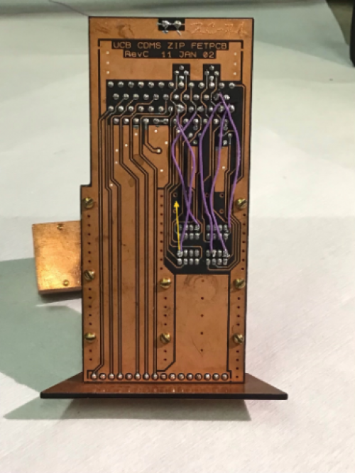 The channel in question is DIB2pC which is Side1pD. Nick suggests that rather than opening the IVC again we can instead add a feedback resistor on the warm side, where we plug into the DCRC. He estimates that the extra noise will be negligible. |