2016/10/07 (Friday)
| Status: upper 100mK can, 600mK rod, upper IVC are reinstalled. All mixture in dump. MB vacuum jacket has been pumped out. | |
| 0935 | Remove Cf source from on top of G101c in clean room and return source to safe |
| 1335 | Remove G101c from purge and put in bag for transport to wire bonding lab |
| 1350 | Remove G101c from bag in wire bonding lab. Exposed to unclean lab for 15 minutes. |
| 1400 | Rebond DIB 1 Side 1 pA |
| 1420 | Bring G101c to clean room and remove from bag. |
Electrical checks:
- DIB1: all good, agrees with Monday
- DIB3: all good, agrees with Monday
- DIB4: all good, agrees with Thursday
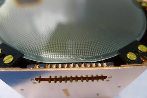 |
| Repaired bond on DIB1 Side 1 pA |
|---|
| 1435 | Return G101c to purge |
|---|
From studying the HV board pinout spreadsheet found here, below is the scheme for the HV board connections. The connections are followed from detector to HV output showing both of the two board configurations.
| Side 1 channels | Side 2 channels | DIB connections | HV board input | Readout 1, Bias 2 HV output | Readout 2, Bias 1 HV output |
|||
|---|---|---|---|---|---|---|---|---|
| TES4 | pA | DIB1 | CONN 1 | CONN 4 | pA | |||
| TES3 | pB | DIB1 | CONN 1 | CONN 4 | pB | |||
| TES2 | pC | DIB1 | CONN 1 | CONN 4 | pC | |||
| TES9 | pD | DIB1 | CONN 1 | CONN 4 | pD | |||
| LEDs | DIB1 | CONN 1 | CONN 4 | LEDs | ||||
| pA | DIB3 | CONN 3 | CONN 5 | pA | ||||
| TES11 | pB | DIB3 | CONN 3 | CONN 5 | pB | |||
| TES5 | pC | DIB3 | CONN 3 | CONN 5 | pB | |||
| pD | DIB3 | CONN 3 | CONN 5 | pD | ||||
| LEDs | DIB3 | CONN 3 | CONN 5 | LEDs | ||||
| pA | DIB4 | CONN 2 | CONN 4 | pA | ||||
| TES8 | pB | DIB4 | CONN 2 | CONN 4 | pB | |||
| TES1 | pC | DIB4 | CONN 2 | CONN 5 | pC | |||
| TES0 | pD | DIB4 | CONN 2 | CONN 5 | pD | |||
| LEDs | DIB4 | CONN 2 | CONN 5 | LEDs | CONN 4 | LEDs | ||
Note that in both configurations, DIB4's LEDs are accessible, but DIB1's LEDs are only accessible for Readout Side 1 and DIB3's LEDs are only accessible for Readout Side 2. So for wiring the four LEDs to the DIBs there are a few options:
- wire two to DIB4, one to DIB1, and one to DIB3. Then in either case 3 LEDs are accessible.
- wire two to DIB4, two to DIB1. Then four LEDs are accessible in the Readout 1 case (which we'll use more often) but only two LEDs are accessible in the Readout 2 case.
- wire two to DIB4, and the other two to both DIB1 and DIB3, by splitting the connections. Then all four will be accessible in either mode.
Option 3 is maybe best but it would mean more wires and soldering to more extender pins.
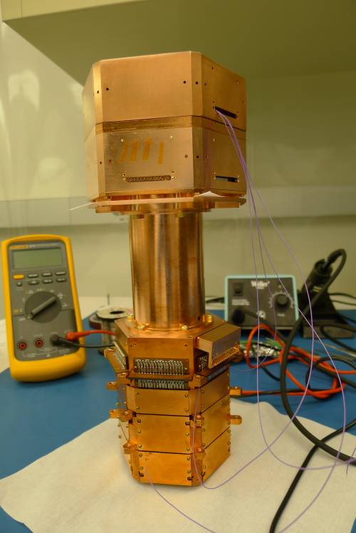
From left to right (with tower upright), the tower face pins are numbered 1-16. Pin 9 and Pin 10 are LED1&2.
 |
| Assembly test |
|---|
| 1745 | Place Cf source on top level of purge cabinet in order to radiate through a layer of plastic to reach G101c in clean room for weekend activation. |
|---|