2016/10/03 (Monday)
| Status: warmup yesterday, mix left to expand from fridge to dump, He gas in main bath vacuum jacket to boil off remaining bath | |
| 0845 | Tower = 190 K, Sorb = >250 K since 02:14, IVC = 2.5 mbar, G1/G2 = 675/615 mbar. |
| 0850 | Pump mix from fridge to dump: close V4, turn on 3He pump, open V6 to 13.8%. Still gate valve, condenser speedivalve, V1, V3, V6, V9 are open. |
| 0915 | Move shield wall back into storage. Dismantle lead castle for 57Co source. |
| 0935 | G2 (Dump pressure) has flattened out to 785 mbar. Stop pumping mix to dump, close all valves, turn off 3He pump. |
| 0945 | Start flowing N2 through MB using LN2 transfer tube |
| 0955 | Fill IVC with N2 gas, to about 730 mbar according to the mechanical gauge. Tower = 198 K. |
| 1000 | Let one hose-length of N2 gas into MB vacuum jacket |
| 1025 | Neither letting more gas into vacuum jacket nor flowing gas through MB seem to have improved the warming rate. Tower = 201 K. |
| 1045 | Lower dewar and place plastic bag around IVC as it warms. Tower = 203K. |
| 1108 | Begin pumping out Main Bath dewar jacket with scroll pump. External pressure sensor reads 6.3E-1 mbar. |
| 1230 | Tower = 243 K |
| 1300 | Scroll pump = 46 μbar, MB vacuum jacket = 86 μbar. Switch to pumping on it with turbo pump for a while. |
| 1340 | Tower = 260 K |
| 1340 | Turbo pump = 1.4 μbar, MB vacuum jacket = 54 μbar. |
| 1400 | Tower = 269 K |
| 1400 | Turbo pump = 1.0 μbar, MB vacuum jacket = 40 μbar. Stop pumping out vacuum jacket to lower Dewar all the way. |
| 1410 | Conducting electrical check at 265K. DIB2 (readout side) still looks good. We still see the shorts to ground of 40MΩ on SQUID Bias C and of 20MΩ on Feedback C and Feedback Ret. These shorts to ground are higher resistance than we saw after installation, but we are still not room temperature yet, so these may decrease. |
| 1415 | DIB3's electrical check passes just fine. |
| 1445 | Lower Dewar into pit. Remove plastic bag from fridge with Tower around 270 K. Sponge it off a bit. Erect mini-cleanroom around fridge. |
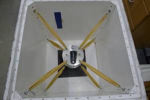
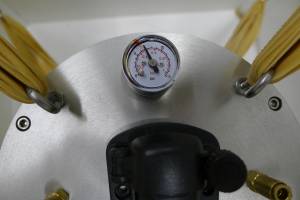
| 1520 | HV#2 (G101c) detector arrives from Stanford in big wooden crate. Pressure gauge reads 7 PSI, somewhat above the red mark. |
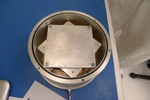
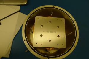
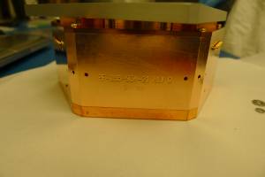
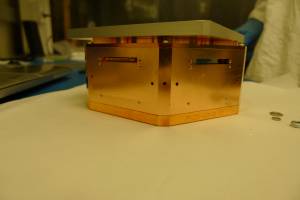
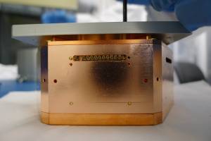
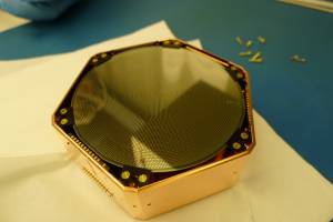
| 1535 | Move G101c detector into clean room and remove from shipping vessel |
from Matt Cherry @ Stanford:
For the shipping, I placed kapton tape on the underside of the connector
lid to prevent copper debris from falling through.
The housing is clamped inside the purge vessel by a stainless plate.
Unfortunately the designed clamping style was unusable after I received it
from TAMU, but I believe my method will be fine.  You'll just need to
remove the four nuts, then the top steel plate.  The lower steel plate is
attached to the connector lid, and the detector can be lifted out with that.
I'm not sure Mark's accelerometer is recording.  The light went off
yesterday, and I could not figure out how to charge it.  I included it, and
the small software disc.
S1:
  d1a=TES1 (100.4), b=TES0 (125.8)                  <<== d1 is UMN DIB 4
  d2a=TES4 (107.2), b=TES3 (59.3), c=TES2 (110.8)   <<== d2 is UMN DIB 1
  d3c=TES5 (34.1)                                   <<== d3 is UMN DIB 3
S2:
  d1c=TES6 (93.3), d=(non-functional TESs) (97.1)***  <<== d1 is UMN DIB 4
  d2d=(non-functional TESs) (79.2)***                 <<== d2 is UMN DIB 1
  d3b=TES11 (26.2)                                    <<== d3 is UMN DIB 3
DIB1 is the one opposite the empty slot. DIB3 is identified because pA and pD are open. Labeling the three DIBs with Kapton tape, one piece on DIB1, two on DIB2, three on DIB 3
TOP is side that DIB slots are closer to (side nearest tower)
Loose socket on DIB3 pin1 (pA return)
| Detector | G101C | DIB | 1 | |
|---|---|---|---|---|
| date/who: | 2016-10-03 | DS NM MF | ||
| +lead | - lead | signal | typical | measured |
| 1 | 2 | QET A | 100 to 200 Ω | 108.3 Ω |
| 3 | 4 | QET B | 100 to 200 Ω | 59.5 Ω |
| 5 | 6 | QET C | 100 to 200 Ω | 99.2 Ω |
| 7 | 8 | QET D | 100 to 200 Ω | 89.3 Ω |
| 9 | chassis | LED1 Rforward | 8 to 9 MΩ | open |
| 9 | chassis | LED1 Vforward | 1.0 to 1.1 V | OL V |
| chassis | 9 | LED1 Rreverse | <1 nS | open |
| 10 | chassis | LED2 Rforward | 8 to 9 MΩ | open |
| 10 | chassis | LED2 Vforward | 1.0 to 1.1 V | OL V |
| chassis | 10 | LED2 Rreverse | <1 nS | open |
| 11 | 12 | Qo-Qi | n/a | |
| 12 | 11 | Qi-Qo | n/a | |
| 1-8 | chassis | <1 nS | <1 nS |
| Detector | G101C | DIB | 4 | |
|---|---|---|---|---|
| date/who: | 2016-10-03 | DS NM MF | ||
| +lead | - lead | signal | typical | measured |
| 1 | 2 | QET A | 100 to 200 Ω | 97.7 Ω |
| 3 | 4 | QET B | 100 to 200 Ω | open |
| 5 | 6 | QET C | 100 to 200 Ω | 92.9 Ω |
| 7 | 8 | QET D | 100 to 200 Ω | 86.1 Ω |
| 9 | chassis | LED1 Rforward | 8 to 9 MΩ | open |
| 9 | chassis | LED1 Vforward | 1.0 to 1.1 V | OL V |
| chassis | 9 | LED1 Rreverse | <1 nS | open |
| 10 | chassis | LED2 Rforward | 8 to 9 MΩ | open |
| 10 | chassis | LED2 Vforward | 1.0 to 1.1 V | OL V |
| chassis | 10 | LED2 Rreverse | <1 nS | open |
| 11 | 12 | Qo-Qi | n/a | |
| 12 | 11 | Qi-Qo | n/a | |
| 1-8 | chassis | <1 nS | <1 nS |
| Detector | G101C | DIB | 3 | |
|---|---|---|---|---|
| date/who: | 2016-10-03 | DS NM MF | ||
| +lead | - lead | signal | typical | measured |
| 1 | 2 | QET A | 100 to 200 Ω | open |
| 3 | 4 | QET B | 100 to 200 Ω | 26.0 Ω |
| 5 | 6 | QET C | 100 to 200 Ω | 33.9 Ω |
| 7 | 8 | QET D | 100 to 200 Ω | open |
| 9 | chassis | LED1 Rforward | 8 to 9 MΩ | open |
| 9 | chassis | LED1 Vforward | 1.0 to 1.1 V | OL V |
| chassis | 9 | LED1 Rreverse | <1 nS | open |
| 10 | chassis | LED2 Rforward | 8 to 9 MΩ | open |
| 10 | chassis | LED2 Vforward | 1.0 to 1.1 V | OL V |
| chassis | 10 | LED2 Rreverse | <1 nS | open |
| 11 | 12 | Qo-Qi | open | |
| 12 | 11 | Qi-Qo | open | |
| 1-8 | chassis | <1 nS | <1 nS |
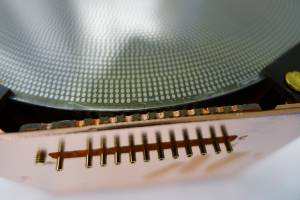
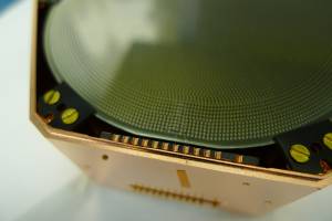
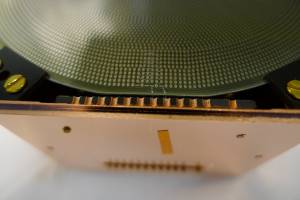
Photographs of DIBs on both sides reveal no LEDs installed on DIBs.
DIB4 pB (side1) broken wirebond is visible.
DIB4 pA and pB (side1) were supposed to be bonded to pC and pD, and it actually looks like it would have been easier to do them that way, bonds wouldn't have to be as long.
| 1640 | Put detector G101c into purge cabinet |
|---|---|
| 1715 | Tower = 283 K |
 |  |  |  |
 |  |  |  |
| Side 2 CW from lower left: DIB1, DIB3, DIB4 |
|---|
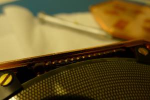 | 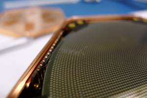 | 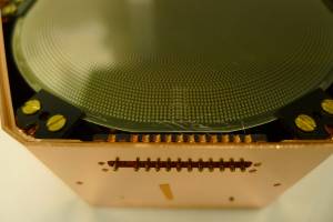 |  |
| Side 1 DIB4: Pin3 (pB ret) has broken bond | Side 1 DIB1 | Side 1 DIB3 | |
|---|---|---|---|
 |  | 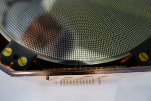 | 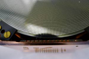 |
| Side 2 DIB1 | Side 2 DIB4 | Side 2 DIB3 | |
|---|---|---|---|