2016/10/10 (Monday)
| Status: Cans reassembled, ready for tower installation. Detector repaired and ready to install with LED holder on tower. All mixture in dump. MB vacuum jacket has been pumped out. | |
| 0825 | Remove Cf source from near G101c in clean room and return source to safe |
| 0855 | Remove G101c from purge cabinet for tower assembly |
| 1000 | Stack is now assembled. Used the crown from G101c and the lid from G101c. One of the threaded holes to attach crown to tower connector was bad so we only used 5 screws. The thermometer is mounted inside the source holder adjacent to the LED boards. |
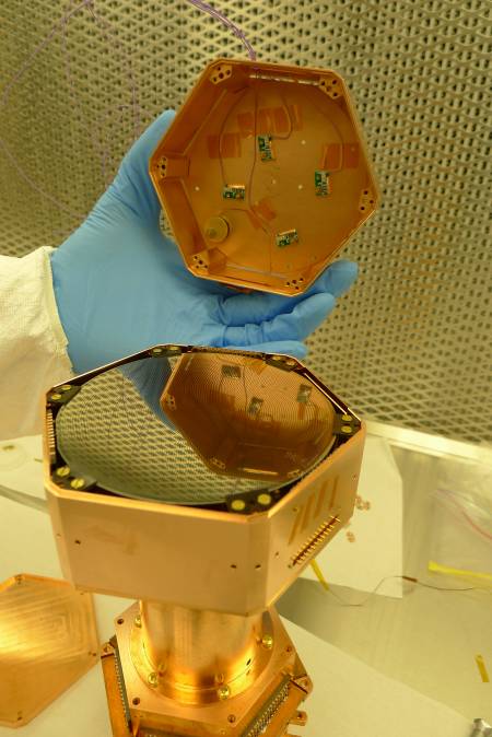 |
| Orientation of LEDs |
|---|
| 1010 | Wipe down clean tent. |
|---|---|
| 1045 | Solder the wires from the four LEDs to pins 9 and 10 of two side coax extenders. Used a very small amount of solder so they'd be easily removable. Plugged these into the sides with DIBs 1 and 4 (that's option 2 from Friday - all four LEDs will be powerable in Side 1 Readout mode but only two in Side 2 Readout mode). |
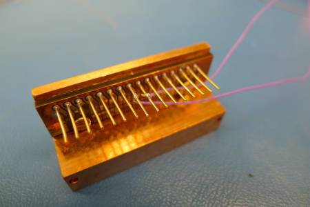 | 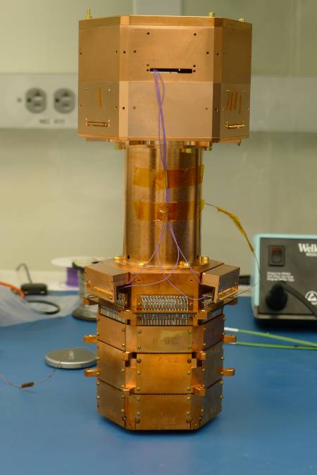 |
| LED wires soldered to pins note: there's a mistake here, pin 8 soldered, s/b pin 10 - later fixed | Assembled tower with LED wires |
|---|
| Side 1 channels | Side 2 channels | DIB connections | HV board input | Readout 1, Bias 2 HV output | Readout 2, Bias 1 HV output |
|||
|---|---|---|---|---|---|---|---|---|
| TES4 | pA | DIB1 | CONN 1 | CONN 4 | pA | |||
| TES3 | pB | DIB1 | CONN 1 | CONN 4 | pB | |||
| TES2 | pC | DIB1 | CONN 1 | CONN 4 | pC | |||
| TES9 | pD | DIB1 | CONN 1 | CONN 4 | pD | |||
| LEDs | DIB1 | CONN 1 | CONN 4 | LEDs | ||||
| pA | DIB3 | CONN 3 | CONN 5 | pA | ||||
| TES11 | pB | DIB3 | CONN 3 | CONN 5 | pB | |||
| TES5 | pC | DIB3 | CONN 3 | CONN 5 | pB | |||
| pD | DIB3 | CONN 3 | CONN 5 | pD | ||||
| | DIB3 | CONN 3 | CONN 5 | |
||||
| pA | DIB4 | CONN 2 | CONN 4 | pA | ||||
| TES8 | pB | DIB4 | CONN 2 | CONN 4 | pB | |||
| TES1 | pC | DIB4 | CONN 2 | CONN 5 | pC | |||
| TES0 | pD | DIB4 | CONN 2 | CONN 5 | pD | |||
| LEDs | DIB4 | CONN 2 | CONN 5 | LEDs | CONN 4 | LEDs | ||
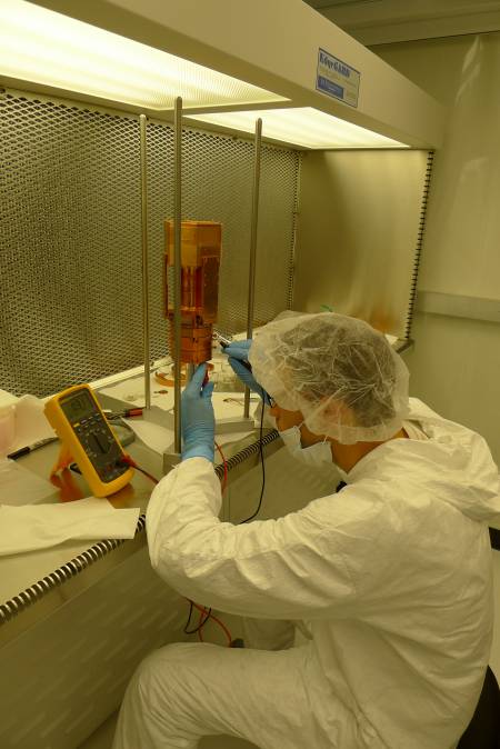
| 1110 | Tower electrical check: |
|---|
| Detector | G101c | DIB | 1 | |
|---|---|---|---|---|
| side coax | ST-3-3 | date/who: | 2016-10-10 | MF NM |
| face | 1 | |||
| +lead | - lead | signal | typical | measured |
| 1 | 2 | QET A | 100 to 200 Ω | 203 Ω |
| 2 | 4 | QETA-B | 100 to 200 Ω | 187 Ω |
| 3 | 4 | QET B | 100 to 200 Ω | 158 Ω |
| 4 | 6 | QETB-C | 100 to 200 Ω | 187 Ω |
| 5 | 6 | QET C | 100 to 200 Ω | 194 Ω |
| 6 | 8 | QETC-D | 100 to 200 Ω | 221 Ω |
| 7 | 8 | QET D | 100 to 200 Ω | 173 Ω |
| 2 | 8 | QETA-D | 100 to 200 Ω | 230 Ω |
| 9 | chassis | LED1 Rforward | 8 to 9 MΩ | 740 kΩ |
| 9 | chassis | LED1 Vforward | 1.0 to 1.1 V | 1.085 V |
| chassis | 9 | LED1 Rreverse | <1 nS | inf Ω |
| 10 | chassis | LED2 Rforward | 8 to 9 MΩ | 740 kΩ |
| 10 | chassis | LED2 Vforward | 1.0 to 1.1 V | 1.086 V |
| chassis | 10 | LED2 Rreverse | <1 nS | inf Ω |
| All pins → Ground | <1.0nS | (Except for LED pins) | all <1 nS | |
| Detector | G101c | DIB | 4 | |
|---|---|---|---|---|
| side coax | ST-3-9 | date/who: | 2016-10-10 | MF NM |
| face | 3 | |||
| +lead | - lead | signal | typical | measured |
| 1 | 2 | QET A | 100 to 200 Ω | inf Ω |
| 2 | 4 | QETA-B | 100 to 200 Ω | inf Ω |
| 3 | 4 | QET B | 100 to 200 Ω | 162 Ω |
| 4 | 6 | QETB-C | 100 to 200 Ω | 189 Ω |
| 5 | 6 | QET C | 100 to 200 Ω | 200 Ω |
| 6 | 8 | QETC-D | 100 to 200 Ω | 232 Ω |
| 7 | 8 | QET D | 100 to 200 Ω | 223 Ω |
| 2 | 8 | QETA-D | 100 to 200 Ω | inf Ω |
| 9 | chassis | LED1 Rforward | 8 to 9 MΩ | 766 kΩ |
| 9 | chassis | LED1 Vforward | 1.0 to 1.1 V | 1.087 V |
| chassis | 9 | LED1 Rreverse | <1 nS | inf Ω |
| 10 | chassis | LED2 Rforward | 8 to 9 MΩ | 760 kΩ |
| 10 | chassis | LED2 Vforward | 1.0 to 1.1 V | 1.081 V |
| chassis | 10 | LED2 Rreverse | <1 nS | inf Ω |
| All pins → Ground | <1.0nS | (Except for LED pins) | all <1 nS | |
| Detector | G101c | DIB | 3 | |
|---|---|---|---|---|
| side coax | ST-3-10 | date/who: | 2016-10-10 | MF NM |
| face | 5 | |||
| +lead | - lead | signal | typical | measured |
| 1 | 2 | QET A | 100 to 200 Ω | inf Ω |
| 2 | 4 | QETA-B | 100 to 200 Ω | inf Ω |
| 3 | 4 | QET B | 100 to 200 Ω | 131 Ω |
| 4 | 6 | QETB-C | 100 to 200 Ω | 155 Ω |
| 5 | 6 | QET C | 100 to 200 Ω | 138 Ω |
| 6 | 8 | QETC-D | 100 to 200 Ω | inf Ω |
| 7 | 8 | QET D | 100 to 200 Ω | inf Ω |
| 2 | 8 | QETA-D | 100 to 200 Ω | inf Ω |
| 9 | chassis | LED1 Rforward | 8 to 9 MΩ | <1 nS |
| 9 | chassis | LED1 Vforward | 1.0 to 1.1 V | n/a V |
| chassis | 9 | LED1 Rreverse | <1 nS | <1 nS |
| 10 | chassis | LED2 Rforward | 8 to 9 MΩ | <1 nS |
| 10 | chassis | LED2 Vforward | 1.0 to 1.1 V | n/a V |
| chassis | 10 | LED2 Rreverse | <1 nS | <1 nS |
| All pins → Ground | <1.0nS | (Except for LED pins) | all <1 nS | |
| 1125 | Put tower back in purge cabinet |
|---|
 |
| 1255 | Polish contact surfaces of adapter plate with Scotch-Brite |
|---|---|
| 1300 | Remove tower from purge cabinet to complete assembly. Scotch-Brite the contact surfaces between the 30 mK ears and the adapter plate. |
| 1330 | Attach adapter plate to tower, using new M3-8 screws (In the past M3-12 screws were used, but they are currently on the 150 mm detector tower). Double-bag tower for installation. |
| 1425 | Tighten IVC screws, top, middle, and stripline tube flanges |
| 1445 | Reattach stripline buckle and heatsink at bottom of middle IVC piece, as on 2015 May 29 |
| 1500 | Polish bottom edge of 30 mK can with Scotch-Brite |
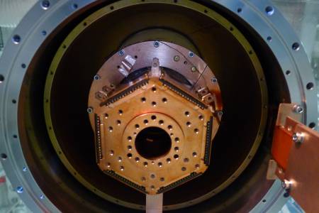
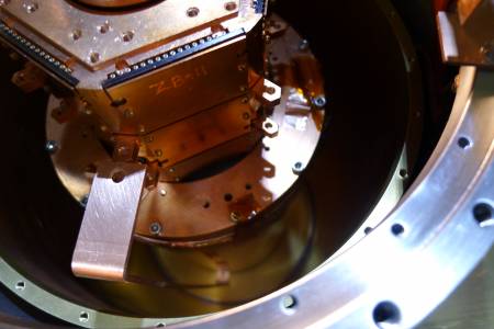
| 1605 | Attach tower to 30 mK can. Plug in tower thermometer. It's a little harder now because the connector on the fridge side does not hang past the edge of the 30 mK can. So first tape it down to the side of the 30 mK can, then plug in the tower side connector, then tape it to the edge of the 30 mK can too. Then wrap the extra wire around the bottom circumference of the 30 mK can and tape down. In most cases I used a “bandaid” piece of kapton tape, so that the sticky part was not on the wire or connector being taped down - the only sticky part was on the can. Tower thermometer is reading 1.0 kΩ at the bridge, looks good. |
 |  |
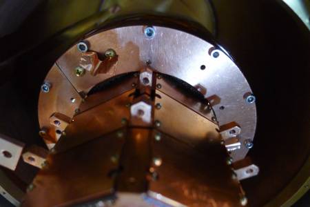 | |
| Photos showing thermometer wire wrapped around bottom of 30mK can and adapter plate | |
|---|---|
| DIB1 is to the East (toward lab door), DIB3 NW, DIB4 SW | |
| 1730 | Install 100mK stage. Still need to tape up the gaps, stopping for tonight. |
| 1750 | Put Cf-source on IVC can for overnight activation. |