Table of Contents
Run 36
| Table 1: Run 36 setup | ||
|---|---|---|
| Detector | G101b | |
| Tower | T1 | |
| DIB | 1 | 2 |
| Face | 2 | 5 |
| Side coax | ZB1-1-6 | ZB1-1-9 |
| SQUET | ZC70 | ZC23 |
| Stripline | #21 | #19 |
| Readout | DCRCv3 | |
Beta Source Holder
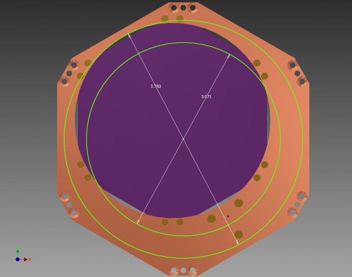
A source holder plate was designed by us and fabricated by our mechanical workshop to hold Queens' Pb-210 beta source and an Am-241 source (engineering drawing). The source holder plate was designed under the assumption that Qi is of diameter 3.071“ and Qo is of diameter 3.780”.
The Pb-210 source was designed to fasten onto the pillars in a 3“ detector housing, so these measurements were used to define the position of the holes and the diameter of the source was overestimated slightly to ensure it fit. Its position is offset from the centre of the plate to allow for the inclusion of an Am-241 source. The following is copied from Wolfgang's email regarding the production of the Pb-210 source:
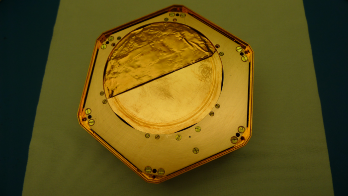
We attached the plate to a cylindrical Al vessel and sealed with a rubber o-ring. In the active side you see a hint of where the o-ring was. The activity would be found only inside this circle.
The Am-241 source is of the same design as that used for Q4 in the 4Q 100 mm device, ie. the collimation hole is offset from the centre. This enables us to position the collimation hole over Qi and further away from the Qi-Qo boundary. We estimate that the collimation hole will result in an event rate of 20 Hz from this source.
The Pb-210 source from Queens arrived on Monday 4th March and Andy from radiation services came round to perform a swab test on Tuesday 5th March. The source was shipped with a 3” holder, and the inside copper surface of this holder that faced the active area of the source was tested. The source arrived with shielding in the form of copper tape across half its surface, therefore reducing its effective activity to around 10 Bq.
After much deliberation, we decided to keep the copper shielding. Therefore, the sources should yield a total event rate of 30 Hz. Additionally, the shielding was placed such that it covered Qo, ensuring the rest of the active surface lay over Qi.
Finally we also decided to place the source over Side 2 as Qi appeared to be quieter during Run 28. This could, however, be due to the DCRC rather than the charge electrodes themselves. The disadvantage with Side 2 is the noisy Qo channel. However, this should not be a problem as we shall be using a smaller trace length of 0.4096 ms and the oscillation in the baseline appears to be of a longer period. Additionally, something may have caused Qo to behave this way during Run 28, and as we do not know the cause, we cannot say with certainty that the oscillations would reoccur.
| Figure 1: Sketch of Assembled Beta Source Holder. Circles represent boundaries of Qi & Qo. |
|---|
 |
| Figure 2: Assembled Beta Source Holder. |
|---|
 |
Cold Hardware Issues
Broken Qo Bias Trace on Stripline 20
Initially, stripline 20 was plugged into SQUET card ZC-70, which in turn was connected to DIB 1. During an electrical check before sealing up the IVC, Qo bias on DIB 1 was found to be open. Neither a tower level continuity check nor an electrical check of SQUET card ZC-70 showed any signs of problems. A 1 Ω resistor was plugged across stripline sockets on the cold end, and continuity checks were performed from the breakout box. The Qo bias trace was indeed severed, and this was confirmed after opening the ebox and conducting continuity checks when touching the solder on the back of the connectors.
No amount of twisting or turning the stripline resulted in a reconnection, indicating that this may be a different problem from that which plagued stripline 21 during the last run. It is uncertain what the cause of this could be, and additionally it is not known if the problem will get worse over time affecting other traces. It is possible that the next traces to fail will be 8 (Qo drain, FET card pin 22), 9 (QET C Return, FET card pin 9), 11 (QET C Return, FET card pin 8) & 12 (LED 2, FET card pin 20). If this remains stable and we only lose Qo bias, we can recover this stripline using an interface board in a future run.
Another continuity check was performed after the run (ie. after a thermal cycle) to determine if the damage had spread. Qo bias was still the only severed trace.
Changes to Facilitate the Use of Stripline 21
As a result of the above, and having determined that sandwiching stripline 21 between two copper sheets was unlikely to work as the two ends of the break may move away from each other due to thermal contraction during cooldown, three possible ways to proceed remained:
- Use stripline 21 (the really broken one) and don't do anything. Although QET D is severed, QET D Return isn't, and if the purpose of this connection is to simply ground the grounded electrode, this should be fine. However, there is probably some reason why this wouldn't work.
- Use stripline 21 (the really broken one) and short Pins 29 (QET D) to 18 (QET C). The failure probability for QET C is pretty large. Alternatively or additionally we could short Pins 46 (QET D Return) to 13 (QET A Return), whose trace is closer to the edge of the stripline.
- Use stripline 20 (Qo bias severed) and short Pins 21 (Qo bias) to 24 (Qi bias). This means by setting Qi's bias, Qo's is also set.
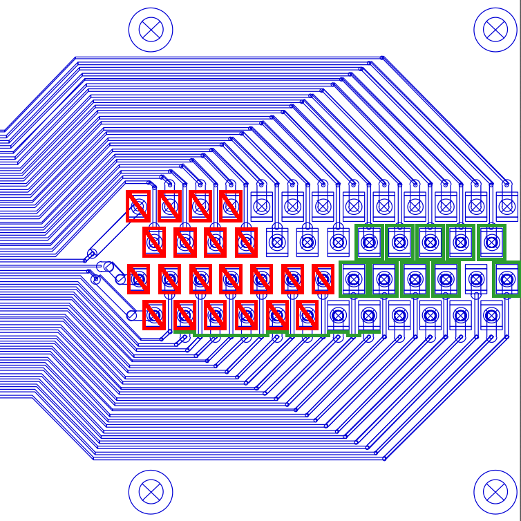
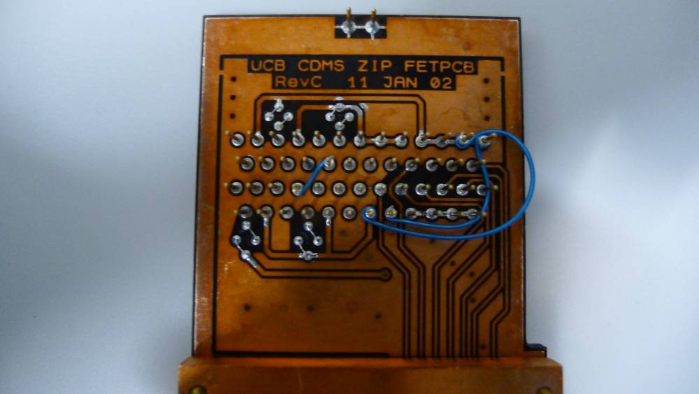
Option 3 would not allow for Qi and Qo to be run at different biases if this was determined to be desirable during the run. Option 2 is safer than option 1, and hence has been chosen. Fig. 3 shows the pins on stripline 21 connected to broken traces in red. Those important for this run are shown in green. A wire-wrap and 30 AWG wire were used to short pins on SQUET card ZC-70 as detailed in Table 2 and illustrated in Fig. 4.
| Figure 3: Stripline pins showing broken ones in red and important ones in green. Only one QET D Return line needs to survive, so they have been indicated by a single green line tied together. |
|---|
 |
| Table 2: Shorting scheme for stripline 21. | |||||||
|---|---|---|---|---|---|---|---|
| From | To | ||||||
| Signal | FET card pin | Trace | Condition | Signal | FET card pin | Trace | Condition |
| QET D | 29 | 32 | severed | QET C | 18 | 16 | in danger |
| QET D Return | 45 | 39 | in danger | QET A Return | 12 | 3 | safe |
| QET D Return | 46 | 41 | in danger | QET A Return | 13 | 1 | safe |
| Figure 4: Connector on SQUET card ZC-70 displaying shorted connections. |
|---|
 |
It was decided to short QET D to QET C to check the integrity of QET D/QET A Returns during cooldown (as a semiconductor, germanium ceases to conduct at lower temperatures, therefore measuring the resistance between Qi/Qo biases and QET A/QET D Returns would not provide a good indication of continuity at 4.2 K).
Electrical checks indicate that the connections appear to have held together during cooldown.
Fridge Leak
Circulation, and therefore data taking, was interrupted at least every other day by blockages in our fridge lines. There is a significant leak in our lines and we suspect that it is in the IGH. The leak seems to start building before the LN2 cold traps, and once a large enough contamination builds up the He cold trap develops a large blockage that causes the pressures in G1 and G2 to rise rapidly and the temperature of the mixing chamber to drop. Unfortunately, we cannot predict when a blockage will occur, because G1 and G2 will gradually increase over the period of a day or two and then randomly spike.
Cleaning the cold traps is a huge time sink. It usually requires 6 hours of laboratory work/processes to be done, and then we have to let the fridge settle back down to a base temperature, which is another 2-3 hours. This is because when a blockage occurs, we have to stop circulation, and isolate the mixture in the fridge and pump what's remaining behind the exhaust of the He-3 pump. Then we have to pull out all three cold traps and clean them all. We weren't able to switch cold traps for circulation before a blockage occurred because we have a leaky valve behind cold trap 1. To correct the problems introduced by the leaky valve, after one instance of blockage occurring, we warmed up to 7 K and installed a manual speedivalve behind cold trap 1. This created the opportunity for us to switch cold traps mid-circulation and continue running for almost a day before making the switch. We also tested out cleaning one LN2 cold trap while still circulating. The amount of He3-He4 mixture lost through this process is unknown, and it's not yet a fully approved method to clean cold traps mid-run. However, we are moving forward in improving our fridge's continuous circulation. Despite the leak we were able to reach 60mK and continue towards data taking.
DCRC Issues
The DCRC was our final downfall in this run. We'd had problems previously with the DCRCs (see Run 34). The fridge was on its last breath (that we were allowing it for the run) and when we powered up the DCRCs to take an overnight run, DCRC32 was showing flat-lined signals:
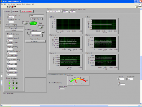
We'd seen this problem before with DCRC33 and DCRC31 plugged into Dib 1, and DCRC33 intermittently with Dib 2. To attempt to correct the flat-lined signal, the following tests were conducted before :
1) Turn on the FET heater in case channels have railed.
2) Reset the clock via putty session.
3) Disconnected and reconnected power to either DCRC32 or to both boards.
After this, DCRC32 refused to make a connection. Then the following tests were done:
4) Disconnecting and reconnecting power to the switch.
5) Disconnecting and reconnecting the boards.
6) Switching which power cables were connected to which boards.
7) Switch the port connected to DCRC32 from 5 to 8 (another port with PSE Power disabled.)
When we did tests with DCRC33, we found that its connection was again intermittent. Tests from the ebox and on the bench showed that DCRC32 and 33 can be partially powered up. However, the +/- 15 V power supply is not. DCRC33's charge amplifier could be powered up some of the time, but DCRC32's never did. It seems the problem is in the software not the hardware. DCRC31 had a similar/same failure mode in which the +/-15V power supply turned off and the board reset the connection. It's starting to seem that the problem that we thought lay mostly in the switch actually lies within the boards and the software.
Data
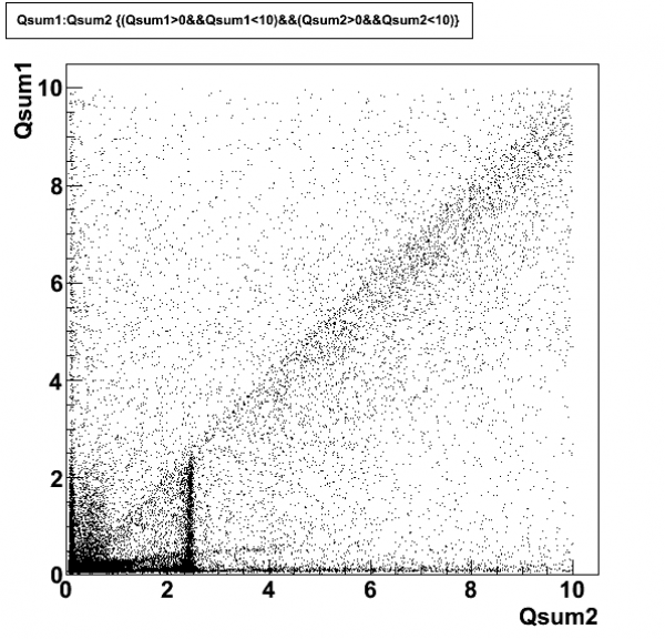
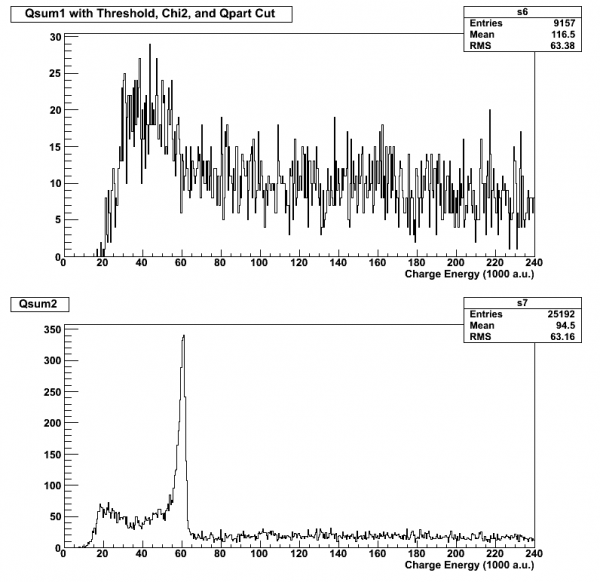
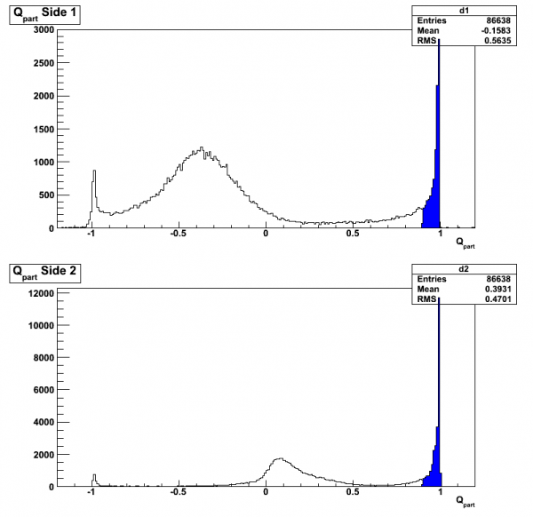
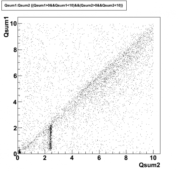
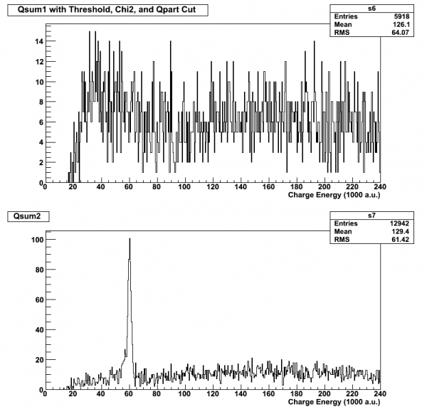
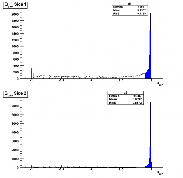
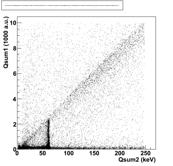
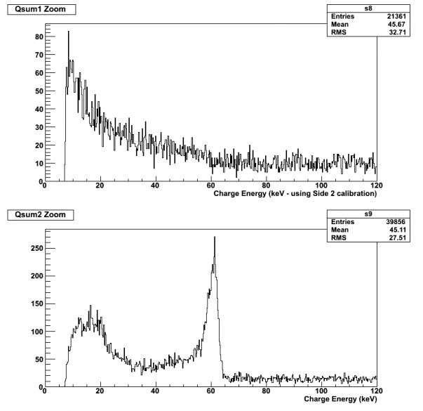
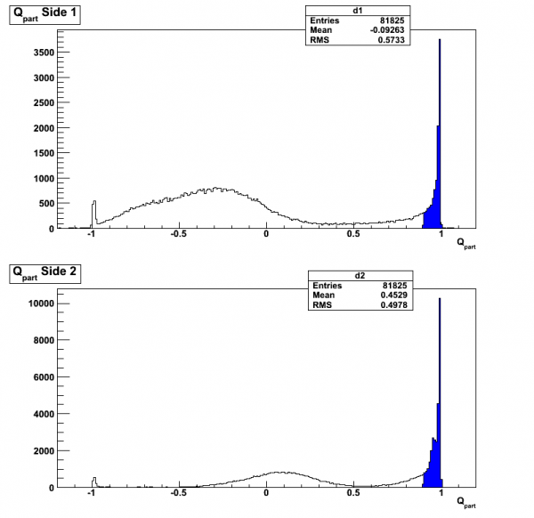
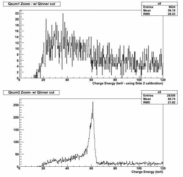
As mentioned above, in this run we've incorporated a Pb-210 source. A large majority of particles coming from this source should be betas < 20 keV. However, in the past we have had trouble seeing events in that low energy range. We decided to push our trigger threshold lower, knowing that it would definitely incorporate more noise events, in hopes to see events from 10-20 keV. We did three tests using different trigger configurations: an OR trigger, an AND trigger, and Qi Side 2 only trigger.
Board Configuration: DCRC32 in Dib1 and DCRC33 in Dib 2.
Bias: +/- 4 V for Dib 1/2.
Trigger Level: 25 ADC with DCRC32, 32 ADC with DCRC33.
Run Time: 30 minutes
| Test 1 : OR Trigger between Qi on Side 1 and Side 2 |
|---|
| Fig. 1: Qsum1 vs. Qsum2 - no cuts. | Fig. 2: Charge spectrum, with threshold, qpart, and chi2 cuts. |
 |  |
| Fig. 3: Qpart - no cuts. |
 |
| Test 2 : AND Trigger between Qi on Side 1 and Side 2 |
|---|
| Fig. 4: Qsum1 vs. Qsum2 - no cuts. | Fig. 5: Charge spectrum, with threshold, qpart, and chi2 cuts. |
 |  |
| Fig. 6: Qpart - no cuts. |
 |
| Test 3 :Trigger on Qi Side 2 only |
|---|
| Fig. 7: Qsum1 vs. Qsum2 - Chi2 cut only. | Fig. 8: Charge spectrum, with threshold and chi2 cut. |
 |  |
| Fig. 9: Qpart - no cuts. | Fig. 10: Charge spectrum, with threshold, chi2 cut, and Qinner cut. |
 |  |
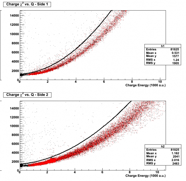
| Fig. 11: Chi2 vs. Charge [1000 a.u.] |
 |