Table of Contents
Run 35
SQUET card ZC-28 was removed due to known problems with phonon channel C. It was replaced with SQUET card ZC-70, which was removed from DIB 3. SQUET card ZC-13, which had recently arrived from Berkeley, was plugged into DIB 3. Unfortunately, due to problems with maintaining base temperature, only Tc measurements and IbIs curves were taken for phonon channel C2. Additionally, broken traces on stripline 21 resulting in the loss of three phonon channels on Side 2 did not provide much of an incentive to carry out the labour-intensive process of cold trap cleaning every couple of days, which was necessary to maintain a reasonably low base temperature. Finally, the lowest temperature reached was 73 mK, which was close to the Tc for channels D2 & C3 on Side 1. Although it could be argued that a run without the outer channel D2 would be useful, C3 is an inner channel.
| Table 1: Run 35 setup | |||
|---|---|---|---|
| Detector | G106a | ||
| Tower | T1 | ||
| DIB | 1 | 2 | 3 |
| Face | 2 | 5 | 6 |
| Side coax | ZB1-1-6 | ZB1-1-9 | ZB1-1-11 |
| SQUET | ZC23 | ZC70 | ZC13 |
| Stripline | #19 | #20 | #21 |
| Readout | DCRCv3 | ||
| Source | 1 Am-241 disk above Ch. C1 | ||
Cold Hardware Problems
Broken Traces on Stripline 21
Upon conducting an electrical check at room temperature before sealing the IVC, QET A to Return on DIB 3 was found to be open. At first it was thought that a pin had missed its socket and thus there was no connection. However, no shorts to ground were found, making this hypothesis less likely.
The SQUET card was removed from the tower and stripline. Tower level continuity checks provided no evidence of a problem. A quick electrical check of the SQUET card itself yielded similar results to those taken upon arrival at Minnesota.
This left the stripline as the only culprit. The SQUET card was plugged back into the tower and stripline, and the electrical check was repeated for DIB 3. The second check revealed that not only was QET A to Return still open, but so was QET D to Return.
Further investigation of the stripline determined that at specific orientations, the connection was restored. It was found that squeezing the stripline a few millimetres above the copper plate also restored continuity and hence the traces must be severed there. It is difficult to believe that mishandling is responsible for this fault, leaving no reason for its development.
As the Am-241 source was facing Side 1 and the two lost channels were located on Side 2, a decision was made to proceed. The cable was patched up with kapton and copper tape in an attempt to hold the cable in a position such that continuity was preserved. However, it was felt that the chances of maintaining continuity as the cryostat cooled were remote.
Indeed this turned out to be the case, as QET A to Return & QET D to Return on DIB 3 were found to be open during an electrical check at 77 K. In addition, SQUID bias A to Return, SQUID bias B to Return, SQUID bias D to Return, Feedback A to Return & Feedback B to Return failed the continuity check. A similar check at liquid helium temeperatures yielded the same result. The complete electrical checkout is shown here (run diary: 2013/02/24). This implies that these traces are now severed, thus leaving a single phonon channel on this DIB. Fortunately, phonon channels A3, B3 & D3 lie on Side 2, so the decision was made to continue to base temperature.
The situation must be solved before further 100 mm IZIPv6 tests can be performed. A few ideas have been floated:
- Obtain a replacement from Berkeley. This is easier said than done as there may not be any spares. The temptation to take one that has been set aside for the Berkeley 400 fridge should be resisted as this would ultimately be self-defeating.
- Uninstall stripline 21 and send it back to Berkeley for repair. If Dennis was around this may have been a possibility. However, it is not known if this is even repairable. Additionall, uninstalling a stripline will force a shutdown for a week. Although installing a new stripline would result in a shutdown for the same period of time, a choice would have to be made between waiting for the repaired stripline to come back to Minneapolis or sealing the fridge back up and shutting down again for a week once the stripline arrived. The schedule may not allow for this.
- Use jumpers to “jump” over the points at which the traces are severed. This is very tricky with a high failure rate. We may end up destroying the entire stripline, although it can be argued that it is useless as it is and will probably deteriorate over time anyway.
- As only one QET Return line is required for each phonon channel, an interface board could be designed to sit between the stripline and SQUET card to divert QET A for example up one of the QET A Return lines. A similar interface board at the warm end can be used to divert the signal back before it hits the DCRC. It is unsure if enough space exists to implement such a solution, and it is likely that further traces will break in the future. This could mean having to redesign the PCBs every run until the QET Return lines are exhausted. That stage may have already been reached.
- Replace the stripline with one of MIT's cables. MIT possesses spools of low and high impedance wire for phonon and charge channels respectively. Simultaneous testing of this wiring scheme with 100 mm IZIP measurements could take place. However, the installation is far more complicated than that for the conventional CDMS-II stripline.
For the next three runs with G101b, G102a & G108a the broken stripline will not matter too much as these ionisation-only detectors feature 2 DIBs. However, a solution to this problem must be found before 100 mm IZIPv6 testing resumes in April.
Cryogenic Problems
Maintaining Stable Base Temperature for Extended Periods of Time
The primary reason for warming up earlier than expected last run was a problem with maintaining base temperature for more than a couple of days. The helium cold trap appeared to clog up frequently and it was thought that the mixture itself was very dirty. Rather than warm up to 4.2 K and cryoclean the mixture for a few hours, we decided to take the opportunity to replace the SQUET card while we were at it and cool back down.
The problem recoccured this run, indicating that a large air leak was present in the mixing chamber lines or contamination from pump oil was entering the system.
Leak Check of Mixing Chamber Lines
IGH Valves 1, 2, 7, 8, 11A & 11B were left open and helium leak checker was connected to vent port. The dump was isolated and its manual valves were closed. Spray tests were conducted on the following flanges:
- Condenser line speedivalve
- Welded joints at top of helium cold traps
- Between copper pipe and hose leading to helium cold trap
- Condenser port on back of IGH
- Nitrogen cold traps 1 & 2 in and out at back of IGH (4 total flanges)
- Four KF10 flanges on nitrogen cold traps
- Two pressure release valves on nitrogen cold traps
- Welded joints on top of nitrogen cold traps
The helium leak rate gradually fell to 6.4E-7 mbar l/s over the course of the spray tests. Liberally spraying the back of the IGH with helium before checking the flanges and joints on the N2 cold traps caused the leak rate to increase to 6.6E-7 mbar l/s. The leak rate then gradually fell to 5.9E-7 mbar l/s as the flanges and joints in the N2 cold traps were spray tested. Liberally spraying the back of the IGH with helium again at the end of the test caused the leak rate to increase gradually to 6.9E-7 mbar l/s. The leak rate then gradually dropped to 5.6E-7 mbar l/s when the helium gas supply was turned off.
This would indicate that there is a small leak somewhere in the IGH. It does not appear to be around the ports, and is likely to be from somewhere inside the IGH. However, the leak does not appear to be very large, and we have seen something similar before. It is doubtful that this is the cause of our now frequent blockages. Having said that, it would be prudent to open up the IGH in the near future and conduct a more thorough leak check.
He-3 Pump's Exhaust Oil Mist Eliminator
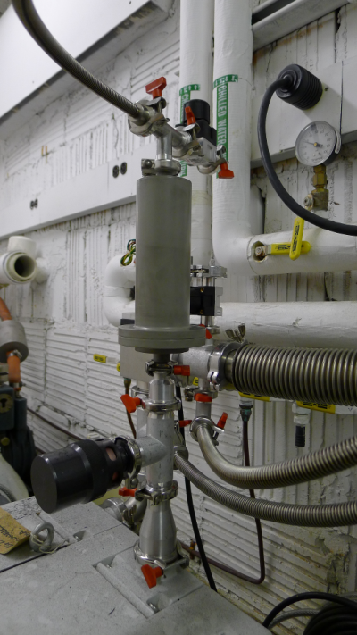
Mixture was removed from the He-3 pump's exhaust, and the cryopump was left in the helium dewar as the transfer was temporary. Photographs of the He-3 pump's exhaust line and oil mist eliminator are shown in Fig. 1. The He-3 pump's oil mist eliminator was removed from the exhaust lines and an attempt was made to pry it apart to drain the oil, as stated in the dilution refrigerator's manual. One socket screw's head is stripped, but it was possible to remove it with a M4 allen key. However, despite best efforts, it could not be pried apart. Closer inspection indicated that the paint had sealed over the gap.
| Figure 1: He-3 pump exhaust line (left) and oil mist eliminator (right). | |
|---|---|
 | 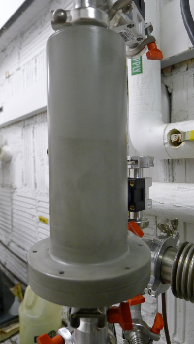 |
Looking at the plumbing, the eliminator has a NW16 port, which would normally be cause for concern. The He-3 pump's exhaust is of size NW40 and the pump has a pumping speed of 65 m3/h (38 CFM). The pump's manual states that the exhaust line should be of at least the same size as the connection port on the pump as a narrower exhaust line can create overpressure in the pump. Having said that, the mixture is not at atmosphere, and the still pressure during circulation is typically very low at 0.1 mbar. Additionally, there is a safety valve at the pump's exhaust before the filter. It is possible that this only poses a problem upon turning on the He-3 pump, and even then for a very short duration. Perhaps the sudden influx of mixture when pumping it into the dump after cryocleaning it for example, may also pose a danger.
The socket head screws were screwed back into place and the oil mist eliminator was restored to its original configuration. Consideration should be given to purchasing a replacement as it does not appear to be possible to drain the oil from this eliminator. It is possible that the oil mist eliminator's filter is saturated, and oil is making its way into the cold traps. However, this it is not possible to confirm this at the moment.
Measuring Properties of Phonon Channel C2
IbIs Measurements
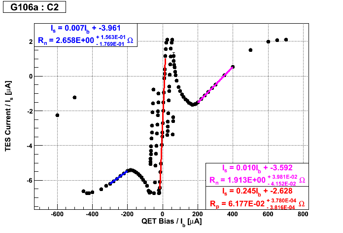
The IbIs curve for phonon channel C2 is shown in Fig. 2. Comparing this curve with those obtained for other channels during Run 34 (run diary: 2013/02/09), the parasitic resistance appears to be an order of magnitude greater than they should be. The normal resistance is also larger than expected by a factor of approximately 2 to 3. At first it was thought that a higher base temperature of 73 mK was to blame. However, this should not affect the normal resistance.
SQUET card ZC-70 was connected to this DIB, and it was used to take IbIs measurements in Run 34 for channel C3 without any issue. Checking through the conversion from Vs to Is yields no errors, so we are at a loss as to what could be the cause.
| Figure 2: IbIs for Phonon Channel C2 at 73 mK. |
|---|
 |
Tc Measurements
Changing the SQUET card also facilitated the measurement of phonon channel C2's Tc, which is given in Table 2. Tcs for other channels taken during Run 34 are available here.
| Table 2: DIB 2 Tc Measurements | ||||||||
|---|---|---|---|---|---|---|---|---|
| Peak-to-Peak Amplitude [mV] | Tc (T increasing) [mK ± 0.2 mK] | Tc (T decreasing) [mK ± 0.2 mK] | ||||||
| Channel | Side | Output Gain | Before Transition | After Transition | Start | Stop | Start | Stop |
| C2 | 2 | 1 | 150 | 9 | 84.5 | 85.2 | 85.3 | 84.0 |