Table of Contents
Summary of Flexible Side Coax Tests with TexCal Cable : Runs 24, 25 & 27
The following is a quick summary of the main findings of our work at the present time. David has submitted his undergraduate thesis, which contains more details. You can download it here. Alternatively, you can find it on the K100 Publications & Theses page.
Additionally, individual run summaries are available here: Run 24; Run 25; & Run 27.
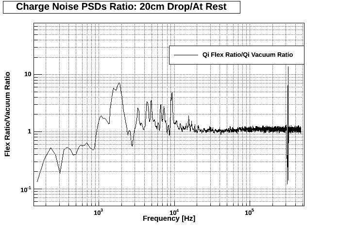
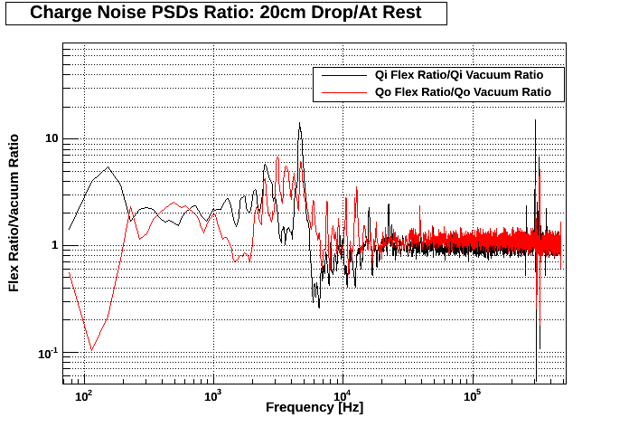
Fig. 1, 2 & 4 below are ratios between the flexible and vacuum side coaxes '20 cm Drop Test'/'At Rest' PSDs. In other words:
- Take 20 cm Drop Test PSD for each channel (Qi & Qo flexible, and Qi & Qo vacuum).
- Take At Rest PSD for each of the aforementioned channels.
- Divide 20 cm Drop Test PSD by At Rest PSD for the aforementioned channels. This will yield one single plot for each of the aforementioned channels.
- Divide the resultant plot for Qi flexible by that for Qi vacuum. Do the same for Qo flexible and vacuum. Bob's your mother's sister's fella.
Run 24
SCAB and SCUHBA extracted from vacuum side coax and TexCal cable soldered between them.
There was a disconnection in the Qo flexible channel, hence the better-than-average PSD. Therefore, only Qi channels are compared in Fig. 1. The susceptibility of the flexible side coax to microphonics appears to be similar to that of the vacuum side coax.
| Figure 1: Flexible/Vacuum Side Coax PSD Ratio for Qi from Run 24. |
|---|
 |
Run 25
New SCAB designed featuring SMD components. However, circuit diagram is identical to that used in a vacuum side coax (ie. 300 pF coupling capacitor, 40 MΩ feedback resistor chain, and 40 MΩ bias resistor chain). The same SCUHBA was used as that in the previous test.
The purpose of this test was to determine how much worse SMDs are. We do not ave access to a wire bonder in a clean room facility, but can easily bring a soldering iron into our clean room!
Please see Fig. 2. The introduction of SMD components appears to have caused a greater susceptibility to microphonics.
One possibility is that the MillMax pins themselves may be to blame. MillMax no longer carry the pins we currently use in CDMS as off-the-shelf items. We purchased the closest equivalent we could fin, which have a thinner gold coating:
MillMax pins used in CDMS cold hardware:
Part no.: 0461-0-15-21-11-35-04-0
Shell finish #21 - 20 μ“ gold over nickel
Contact finish #35 - 50 μ” gold over nickel
Pins we used for new SCABs and SCUHBAs we built:
Part no.: 0461-0-15-15-11-27-04-0
Shell finish #15 - 10 μ“ gold over nickel
Contact finish #27 - 30 μ” gold over nickel
| Figure 2: Flexible/Vacuum Side Coax PSD Ratios for Run 25. |
|---|
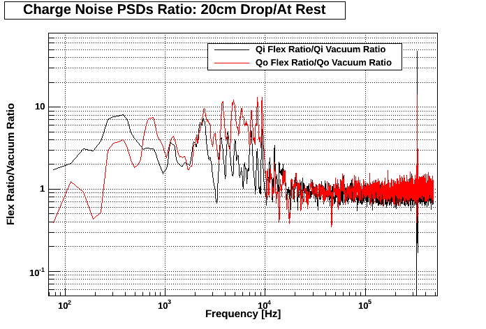 |
It is possible that the pins themselves do not sit well in their sockets. Having said that, results from Run 27 would invalidate such a conclusion.
Run 27
| Figure 3: Circuit diagram for Vacuum Side Coax (left) and Flexible Side Coax used in Run 27 (right). | |
|---|---|
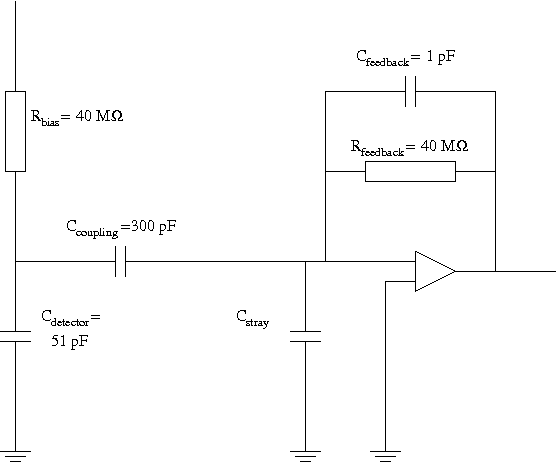 | 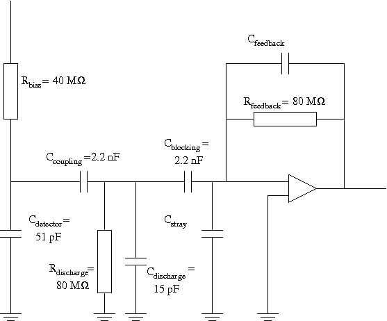 |
New SCAB and SCUHBA designed featuring SMD components. Circuit diagram has changed: 80 MΩ feedback resistor on SCUHBA; 80Ω discharge resistor for cable on SCAB; 2.2 nF coupling capacitor on SCAB; and 2.2 nF blocking capacitor on SCUHBA. A comparison between this circuit and the conventional vacuum side coax one is shown in Fig. 3.
The flexible side coax exhibits significantly higher noise at low frequencies than the vacuum side coax, as shown in Fig. 4. However, the ratios of noise profiles in Fig. 3 are similar between side coaxes. Therefore, despite the higher noise level exhibited by this flexible side coax, the response to induced microphonics was similar to the vacuum side coax.
| Figure 4: Flexible/Vacuum Side Coax PSD Ratios for Run 27. |
|---|
 |
If one could determine why elevated noise levels are witnessed at low frequency (Fig. 5), this model of the flexible side coax may be the direction we should pursue.
| Figure 5: At Rest PSDs from Run 27 taken with DCRC32. |
|---|
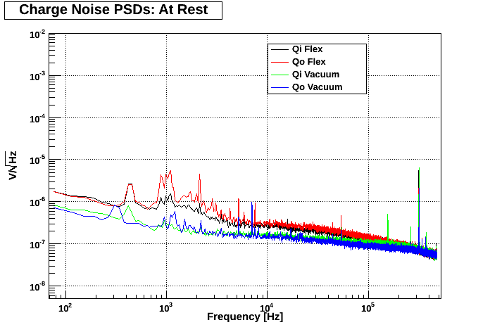 |
Part of the increase can be explained through an increase in charge gains, as measured in Table 1. Additionally, the input capacitance of the circuit has increased due to the presence of two 2.2 nF capacitors in series with the detector. This would result in a slight increase in noise. Finally, upon disassembly, the braid on the SCUHBA side of the cable was barely in contact with the tower/spool. This would imply that there may have been grounding problems, which may explain the peaks at low frequency. The reason the braid was not in contact with the tower/spool was due to the slightly larger SCUHBA (length 543 mils as opposed to 375 mils), meaning that the cable sat a little higher, and thus was inconveniently placed to ensure the braid came into contact with the tower/spool.
| Table 1: Charge Gain Measurements. | ||
|---|---|---|
| Channel | Gain | Gain/4* |
| Qi vacuum | 512.8 | 128.2 |
| Qo vacuum | 472.2 | 118.1 |
| Qi flexible | 582.0 | 145.5 |
| Qo flexible | 615.6 | 153.9 |
| * Factor of 4 from amplifier on DCRC. | ||