Table of Contents
Run 24
Summary
- A fake detector was created with 51 pF capacitors.
- SCAB and SCHUBA were extracted from a vacuum side coax.
- Low noise copper coaxial cable bridged gap between them to form flexible side coax v1.
- The noise performance and susceptibility to microphonics of this side coax was tested during this run and compared with that of a vacuum side coax mounted in the same cryostat.
- The PSDs from the vacuum and flexible side coaxes were found to be comparable.
- Capacitance measurements indicate that the capacitors used to construct the fake detector are relatively stable with temperature.
- Description of future run plans given at the end.
Description of Setup
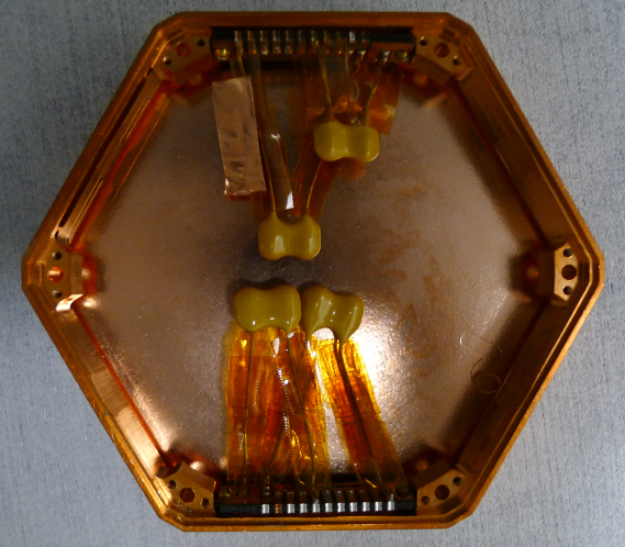
Two DIBs have been mounted in a 1 cm iZIP-style housing as shown in Fig. 1. Each DIB features two 51 pF mica capacitors (Cornell Dubilier CD15ED510JO3F data sheet): one capacitor is soldered between Qi and QET Return A; the other between Qo and QET Return D. One rigid vacuum side coax is attached to one of the DIBs. The other DIB is for the flexible side coax.
| Figure 1: Assembled housing with 50 pF Capacitors. |
|---|
 |
| Figure 2: Assembled Flexible Side Coax v1. |
|---|
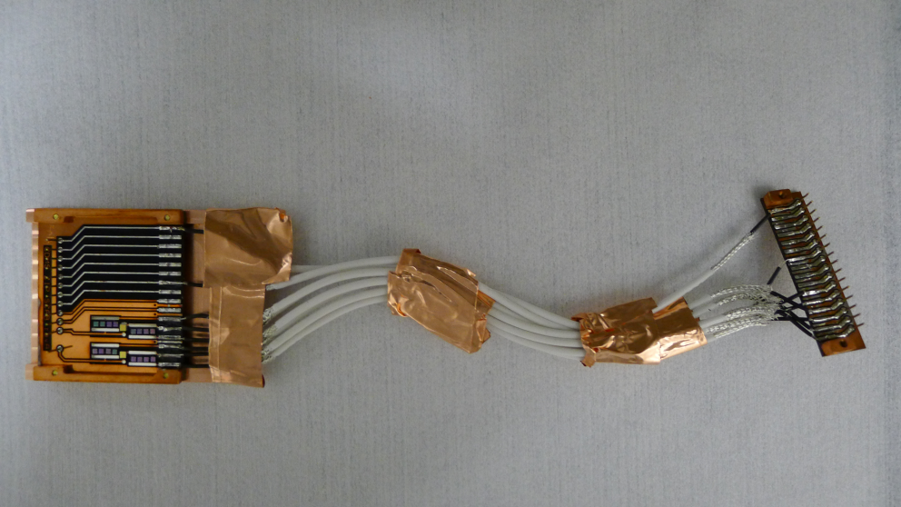 |
The first version of the flexible side coax, shown in Fig. 2, comprises of SCAB and SCHUBA boards that have been extracted from a rigid vacuum side coax. Eight 6”-long, low noise copper wires (the same type as that used during Run 4) bridge the gap between pads on each board. The low noise coaxial cables are manufactured by TexCal (part no.: 250-3820-0000). Only charge pads (ie. pads 1-16), and QET Returns A & D (pads 1 & 7 respectively) have been connected.
To ground the braid, the shield from each cable is soldered to a piece of copper foil (not visible in Fig. 2), which is attached with copper tape to the SCAB's back plate. At the SCHUBA end of the cables, the shield is simply taped to the surface of the tower.
RF shielding is provided by a copper back plate on the SCAB. Both the SCHUBA and the SCAB are separated from the detector housing and tower respectively by copper nut plates that have also been extracted from a vacuum side coax. The SCHUBA does not feature a back plate.
| Figure 3: Assembled Tower with Flexible Side Coax v1. |
|---|
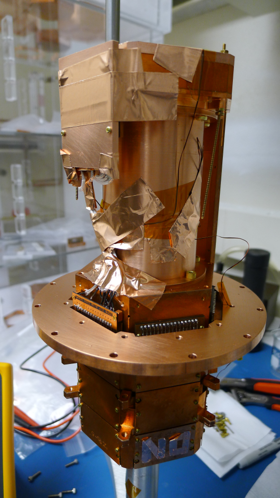 |
The assembled tower is shown in Fig. 3. As the psuedo detector does (should!) not conduct at room temperature, the bias line resistors were checked for continuity between the DIB and end of the tower. The results of the electrical check in Table 1 showed no signs of any problems.
| Table 1: Tower Level Continuity Checks. | ||
|---|---|---|
| Side Coax | ZB1-1-9 | Flexible v1 |
| Tower Face | 5 | 2 |
| Qi Feedback-Qi Gate | 25 nS | 26 nS |
| Qi Feedback-Qi Bias | <0.1 nS | <0.1 nS |
| Qi Bias-Qi (at DIB) | * | 25 nS |
| Qo Feedback-Qo Gate | 25 nS | 26 nS |
| Qo Feedback-Qo Bias | <0.1 nS | <0.1 nS |
| Qo Bias-Qo (at DIB) | * | 25 nS |
| No shorts to ground | ||
* did not check
| Table 2: Run 24 Setup. | ||
|---|---|---|
| Detector | 51 pF mica capacitor | |
| Tower | T1 | |
| Face | 5 | 2 |
| Side coax | ZB1-1-9 | Flexible v1 |
| SQUET | ZC70 | ZC23 |
| Stripline | #20 | #19 |
| Readout | DCRCv3 | |
Charge Noise Measurements
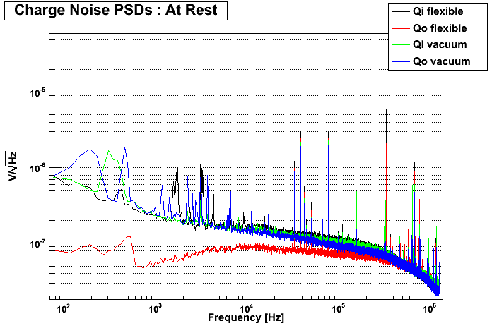
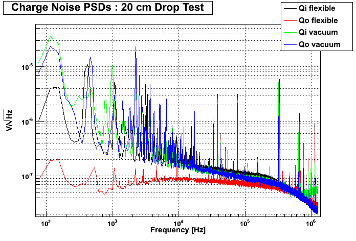
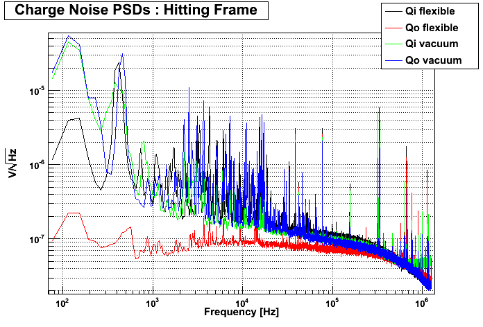
At first, both DCRC boards were installed and the timing link between them was set up. Data was taken both at rest (ie. everything was as calm as possible in the laboratory, no unusual vibrations, etc.) and after dropping a mass from 20 cm above the fridge's frame to induce microphonics. The choice of mass and height was arbitrary, and was found to give a similar response as hitting the frame with a mallet as shown in Fig. 4.
| Figure 4: DCRC33 attached to Flexible Side Coax; DCRC32 attached to Vacuum Side Coax. | |
|---|---|
 |  |
 |
|
For the first test in Fig. 4, DCRC33 was attached to the flexible side coax and DCRC32 was connected to the vacuum side coax. Qo on the flexible side coax has a noise profile similar to that seen at Soudan. As the detector has been simulated with a 50 pF capacitor, the higher noise in the low energy portions of the other spectra cannot be attributed to contamination from pulses.
| Figure 5: DCRC33 attached to Vacuum Side Coax; DCRC32 attached to Flexible Side Coax. | |
|---|---|
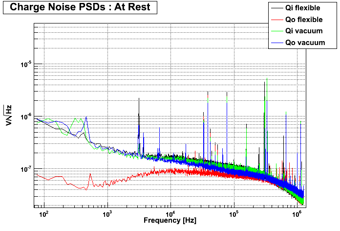 | 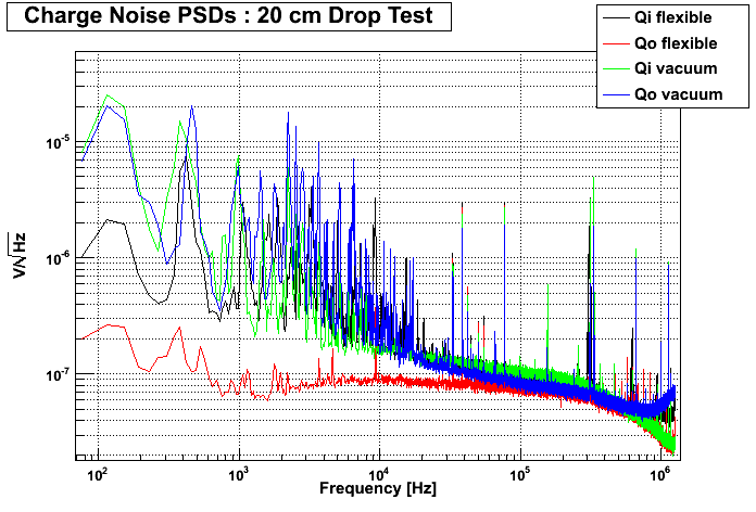 |
When the boards were swapped (Fig. 5), this behaviour did not follow the DCRC boards. In other words, Qo on the flexible side coax still exhibited a relatively impressive noise PSD.
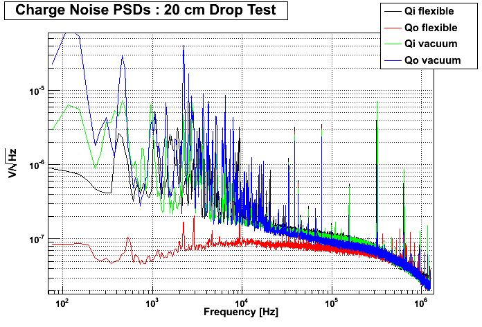
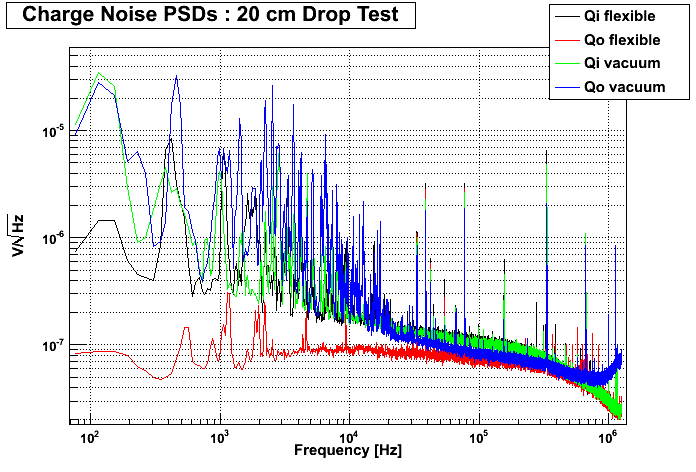
Inducing microphonics through the drop tests indicates that both the vacuum and flexible side coaxes exhibit similar responses. The channel least susceptible to microphonics is Qo on the flexible side coax. This was unexpected. During Run 4, Qi's gate wire in a position #6 vacuum side coax was replaced with the same low noise copper coaxial cable. The results at rest were comparable. However, whacking the fridge with a mallet resulted in little change to Qo's PSD compared with that of Qi.
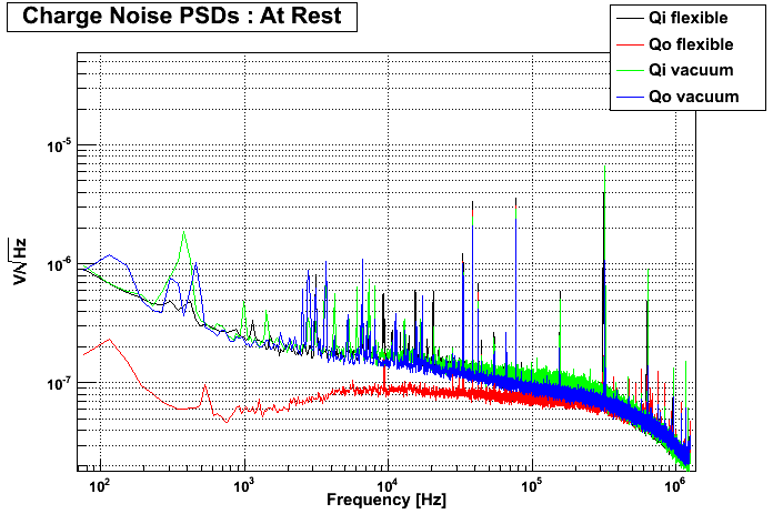
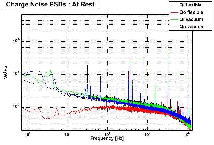
The power supplies on the DCRCs do interfere with each other, and are an additional source of noise. To remove the source, one of the boards was removed and data was acquired with one side coax. The DCRC was then connected to the other side coax and the process was repeated. The PSDs from these tests are shown in Fig. 6 & 7. Both DCRCs seem pretty comparable.
| Figure 6: DCRC32 attached to both side coaxes. | |
|---|---|
 |  |
| Figure 7: DCRC33 attached to both side coaxes. | |
|---|---|
 |  |
In conlusion, it appears as though the flexible side coax's noise performance and susceptibility to microphonics is similar to that of the vacuum side coax. Further discussion of the reasons for the shape of Qo's PSD on the flexible side coax is given in the next section, and for the purposes of this conlusion its results should be ignored. Pulses have been acquired for all the tests described above for further analysis offline if deemed necessary.
Detector Capacitance Measurements
Although the 51 pF mica capacitors used to create this run's fake detector have been utilised before in this fridge, their capacitance at base temperature has not been measured. Although an absolute value is difficult to ascertain, a value relative to room temperature would provide the information we require. Therefore, the capacitance was measured through two tests outlined below.
RC Circuit
A RC circuit was built with a 51 pF capacitor of the same type used in the fake detector in series with a 110 kΩ resistor. A bias of 10 V was applied to the circuit to charge the capacitor, and an oscilloscope was connected across the capacitor to find the time constant.
Long wires were required to insert the capacitor into a dewar of liquid helium. Therefore, to keep the setup consistent between different temperature stages, the long wires were always present when taking measurements. Room temperature measurements were performed on the bench. Measurements at 77 K and 4.2 K were performed by dropping the capacitor into dewars of liquid nitrogen and helium respectively and leaving them to cool for a couple of minutes.
The measurements were repeated 7 times at each tempearture. When converting the time constant to a capacitance, values larger than 51 pF were obtained. The capacitances and resistances of the testing equipment are unknown and the purpose of this measurement is to determine the relative change with temperature rather than an absolute value.
| Table 3: Capacitance Measurements at Various Temperatures. | |
|---|---|
| Temperature | Capacitance [pF] |
| 300 K | 264 ± 15 |
| 77 K | 231 ± 12 |
| 4.2 K | 244 ± 13 |
For comparison, when the longer wires were removed, the capacitance at room temperature was measured as 204 ± 8 pF.
The capacitances at the three temperatures are fairly consistent with one another. The capacitance is expected to decrease with temperature, but the change does not appear to be drastic.
Measuring Charge Gains
Another way to perform this measurement is to send a pulse down the QET Return lines, through the detector and coupling capacitors, and measure the amplitude of the output with the DCRC boards. If the injected pulse is faster than the RC of the ionisation feedback circuit, in other words 40 MΩ × 1 pF = 40 ms (25 kHz), the ratio of output to input (Vout/Vin) scales as Cdet/Cfb. Cdet includes detector, coupling and stray capacitances.
Resistors R01, R10 & R38 were desoldered from the HV DCRC interface boards used during Run 23, and the pads for these resistors were shorted with electrical wire. The HV DCRC interface boards were designed to divert all pins associated with phonon channels to a BNC connector so a higher bias could be applied across the 100 mm detector avoiding the coupling capacitors in the side coaxes. A circuit diagram and PCB schematic are available. In short, this facilitated exciting the setup by sending a pulse through the BNC connection and down the QET Return A & D lines.
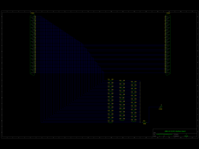
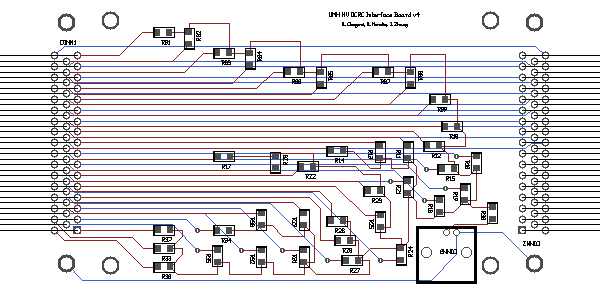
A 1 mV peak-to-peak sine wave of frequency 100 kHz was sent down the QET Return lines and the output was monitored with the DetectorReadout vi. A quick check witht he oscilloscope across QET Return A and Qi Drain confirmed the potential across the detector and coupling capacitors.
Factoring out the gain of 4 from the amplifier, we determined the following charge gains:
| Table 4: Charge Gains. | |
|---|---|
| Channel | Gain |
| Qi vacuum | 128.5 |
| Qo vacuum | 119.4 |
| Qi flexible | 126.3 |
| Qo flexible | 1.89 |
The error on Vout is negligible, and it can be assumed that the error on Cfb (the feedback capacitor) would dominate. Therefore, error analysis is meaningless without knowledge of the latter's magnitude. A script has been written in Mathematica to calculate the detector capacitance. If the stray capacitance is assumed to be 1 pF, detector capacitances between 190 and 225 pF are obtained for every channel but Qo flexible. This shows some agreement with the measurements performed with the RC circuit detailed above. Without a handle on the errors or actual value of the stray capacitance, it is not possible to claim anymore than this.
A low gain is witnessed with Qo flexible. In order to see anything, the amplitude of the sine wave had to be increased by 2 orders of magnitude. This is probably because the 51 pF capacitor acting as the detector is not connected, or in other words the circuit is open. This is confirmed when a pulse was sent down Qo Bias. The pulse was clearly seen after the amplifier. An electrical check between Qo Feedback and Qo Drain/Source showed this line was not severed. A pulse was sent down the QET Return lines and an attempt was made to read it out from Qo Bias. However, the amplitude had to be increased before anything could be seen. It may be safe to assume that the fact a pulse could be seen at all may be due to cross talk.
Therefore, the reason why the PSD for Qo flexible looks so good is because the detector capacitor does not appear to be connected to this line.
Future Plans : Run 25
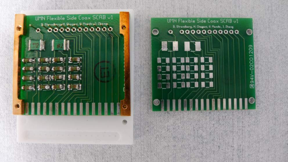
| Figure 8: Finished Flexible Side Coax v1 SCAB (left) and Unsoldered Flexible Side Coax v1 SCAB (right). |
|---|
 |
| Larger image: 3968 x 2232 |
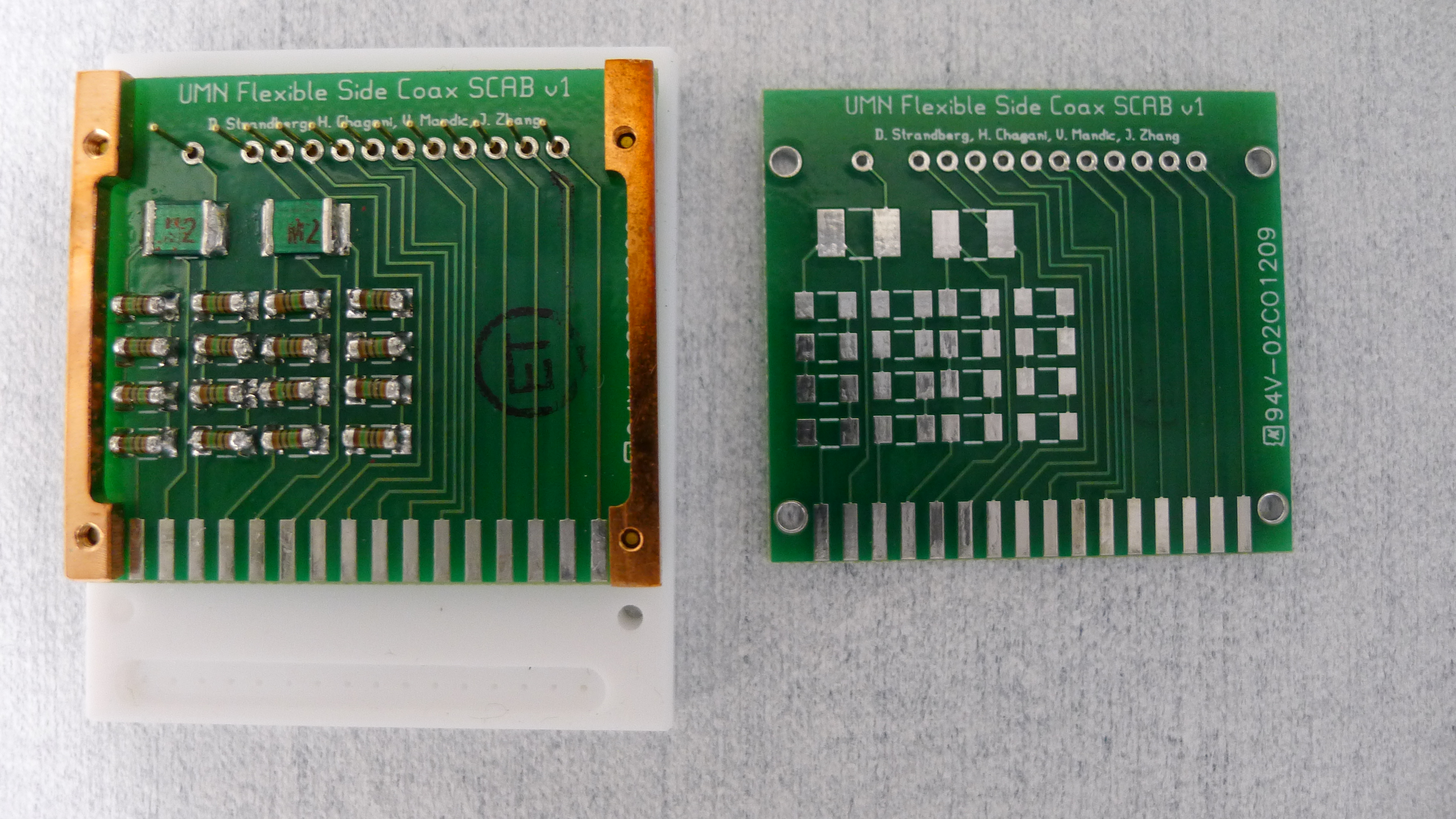
Gerber files
Data sheets: 300 pF mica capacitor Cornell Dubilier MC18FD301J-F & 10 MΩ metal film resistor Vishay Beyschlag MMA02040C1005FB300.
Future Plans : Runs 26 & 27
 |
| Larger image: 2232 x 3968 |
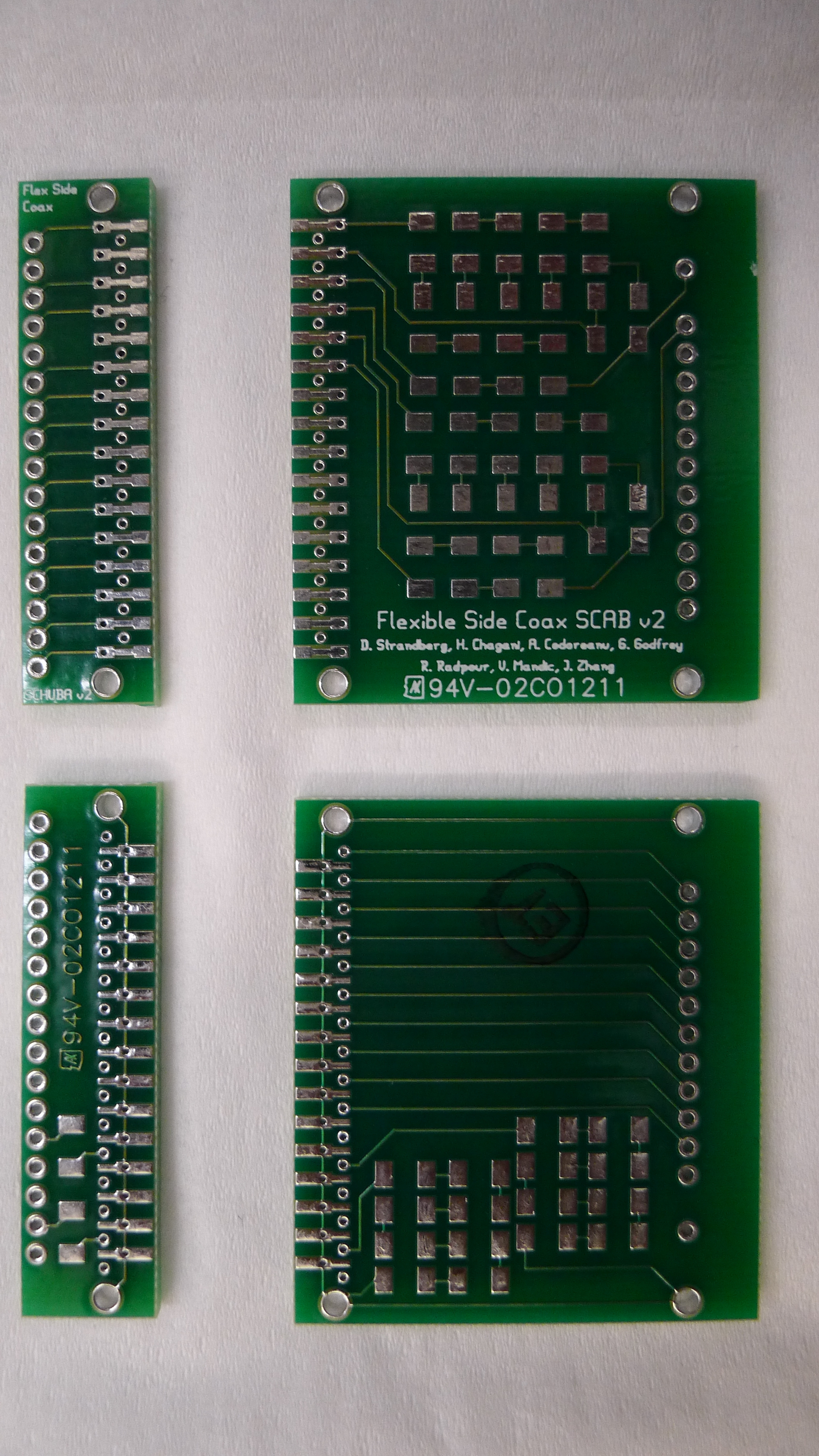
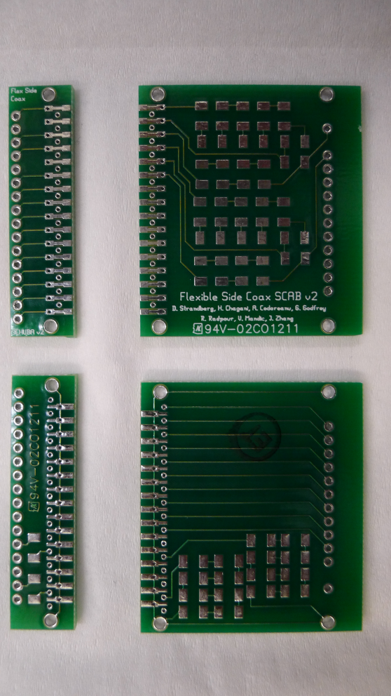
Gerber files: SCAB & SCHUBA.
Data sheets: 2.2 nF CoG/NP0 capacitor AVX 12065A222FAT2A & 10 MΩ metal film resistor Vishay Beyschlag MMA02040C1005FB300.