| Status | Run 76 finished |
| Setup | DCRC33(2)→HV control, NaI trigger signal → DCRCX(4) |
| | IVC disassembled. Stripline tube still in place, plan to remove it today. Refer to 2021 May 12 for photos. |
| 1135 | Remove the clamp between the stripline elbow and the tee, and also the clamp on the side of the tee. Scooch the E-box back a little away from the fridge. Loosen both compression rings, the one on the stripline elbow and the one on the fridge stripline port. |
| 1155 | Lower stripline tube enough so that it is below the top fridge flange. There is still kapton tape covering the hole for the port, so maybe this will help prevent scratches. |
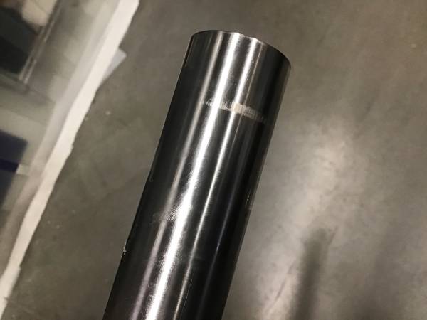
| 1200 | Clean grease off top of tube and inspect for scratches. Looks like there may be some short vertical scratches. |
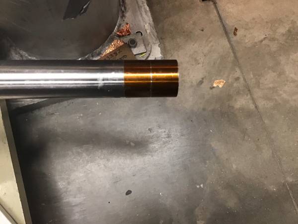
| 1205 | Wrap two pieces of wide kapton tape around the top of the stripline tube in hopes of preventing scratches as it goes past the baffles. There is also still teflon wrapped over the edges of the baffle holes, though some has fallen off. Lower stripline tube completely. Unlike last time we didn't really have any trouble pulling the three stripline tubes through. Probably it's easier as a two-person job. |
| |  |
| |  |
| 1225 | Push striplines upward to allow some slack to pull up the stripline elbow. Unscrew compression ring completely from stripline elbow. Pull up the stripline elbow and tie it to upper section of fridge plumbing to hold it up. Work o-ring out and push it down through port. |
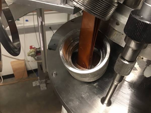
| 1240 | Work o-ring down through all the baffles – have to pull the stripline baffle plates up and down to get them out of the way as you go. Inspect this #222 Viton o-ring – it looks fine as far as I can tell. Feels pretty similar to a new viton o-ring. |
| 1255 | Also remove the o-ring from the fridge port seal. Not sure what material it is. |
| |  |
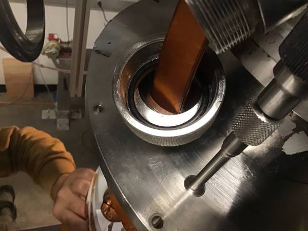
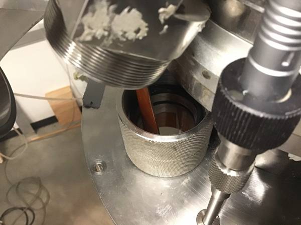
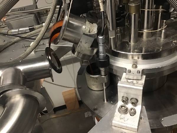
| 1305 | Work a new #222 Buna-N (nitrile) o-ring up the striplines and place it in the compression ring for the stripline elbow seal. Also another one for the fridge port (MB) seal. |
| |  |
| 1310 | Clean the top of the fridge port and bottom of stripline elbow port with methanol. Spread a little vacuum grease on the o-rings. |
| |  |
| |  |
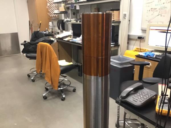
| 1325 | Polish end of stripline tube with scotch-brite and with 1500-grit sanding paper. Hold the scotch-brite/paper around the end and rotate the tube, make sure not to polish at all in the vertical direction. Wipe clean with methanol. |
| |  |
| 1345 | Zach polishes surfaces of IVC upper and middle pieces and cleans indium-seal flanges |
| 1355 | Put three rows of wide Kapton tape over end of stripline tube. Push stripline tube up to just below the fridge flange. Had to retape the striplines together to keep the ends slightly separated to work them through the tube. |
| 1410 | Remove tape at top of tube. Looks like there are some new scratches - short vertical ones along a strip a couple cm wide. Polish with scotch-brite, mostly removes them. Clean the end with methanol, then apply a little vacuum grease. |
| 1415 | Push the stripline tube up the rest of the way, till it engages both o-rings. Tighten the two compression rings a little bit. |
| 1545 | Reconnect the tee at the top of the fridge, and pull the E-box closer to the fridge, near it's original position. This will allow enough slack in the striplines to connect the heatsink at the bottom. |
| 1600 | Examining the fridge thermometer wire connector. This seems to have been causing us trouble, making thermometers at the tower read anomalously high at low temps. (These spurious readings may have also been related to helium films, in some weird way.) There's a teflon-taped and kapton-taped section up a foot or so from the connector, looks like there were maybe solder repairs on two of the four wires. Wires are colored, something like red/gold/green/? - last color maybe looks green too? At the connector there's white rubbery epoxy that we are trying to pull off, so we can maybe resolder this connector. |
| 1620 | Check connections from fridge thermometer connector to thermometer breakout box, with switch set to U02844. Find that connector pins 1/2/3/4 → I+/I-/V-/V+. In other words the two inner pins on the connector should go to one side of the thermometer, the two outer to the other side (that's how I remembered it). All wires read about 150 Ohm. Also checked cross-resistances, all below 0.1 nS. |
| 1625 | Removed most of the white goo from the connector. Decided not to resolder it. Put new pieces of kapton tape over the connector end. Also wrap a piece around the section that appears to have two solder repairs. |
| 1715 | Install upper IVC section. First clean all three indium o-ring surfaces on upper IVC section. Then clean o-ring surfaces on bottom flange on fridge and bottom of stripline tube. Put 1.5mm diam indium o-ring on upper IVC section top flange. Put 1.0mm diam indium o-ring on stripline port of IVC top section. Feed striplines one at a time through stripline port, then raise upper IVC section with 600 mK rod pushed to the middle and feeding fridge thermometer connector through. Attach at top with two screws + washers. Had to adjust the stripline tube upward and the level meter upward. Tighten screws at top and at stripline port in star pattern, tightening many rounds around. Left them pretty tight (till they squeaked), can do some more tomorrow. |