| Status | Run 76 finished |
| Setup | DCRC33(2)→HV control, NaI trigger signal → DCRCX(4) |
| | Stripline tube reinstalled last time. Upper IVC section installed. |
| | 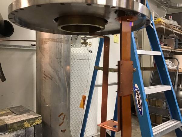 |
| 1405 | Attach upper stripline heatsink to striplines, using two Sharpie marks on striplines for positioning |
| | 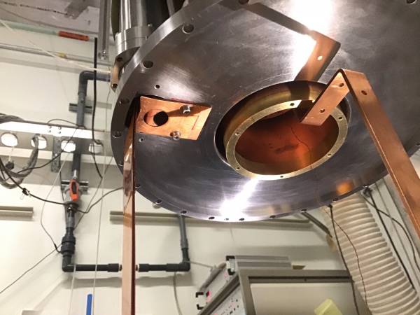 |
| 1410 | Attach upper stripline heatsink and stripline guide to ceiling of IVC, using sharpie marks as guides. |
| 1425 | Polish bottom of MC and bottom edge of coldplate tube with Scotch-Brite, wipe with methanol. |
| 1425 | Polish surfaces of 100mK can, wipe with methanol |
| | 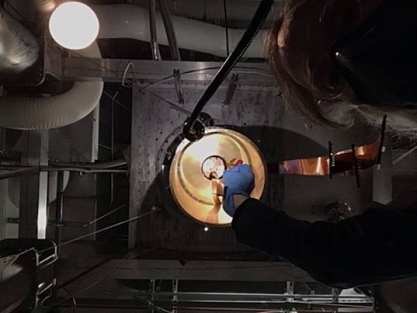 |
| 1440 | Attach the 100mK can (moving the 600mK rod out of the way, and letting the tower thermometer wire dangle in the middle). Attach the six steel bolts with washers and torque them. Used the red T-handled Allen wrench that doesn't have a ball end, screws can balance easily on the end. |
| | 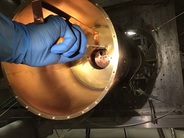 |
| 1445 | Finish torquing the 100mK Can screws |
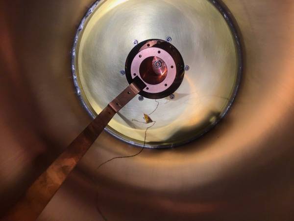
| 1500 | Polish top and bottom of MC spool. Attach spool to MC. First, attach center nut with nut driver, one person holding up the spool and the other screwing on the nut. Then attach and tighten the seven Phillips-head screws. Use long Phillips screwdriver from the clean tent tool kit, screws stay balanced on the end easily. |
| |  |
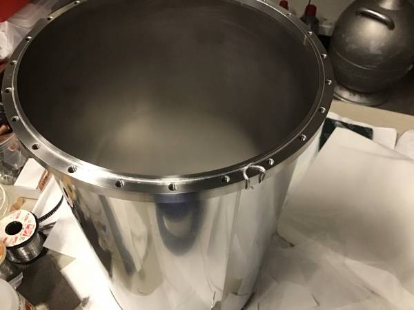
| 1525 | Attach 30 mK can. This is always a bit tricky to get started. This time I found a 10cm long threaded rod and inserted that into one of the spool holes first. Then raise the can and with my fingers up inside and feeling the top of the can, eventually find a hole and raise it around the threaded rod. Then while one person holds it up the other gets one of the other screws going. Tighten and torque all six screws. |
| |  |
| 1550 | Put new 1.5mm diameter indium o-ring on top of middle section of IVC. Install with screws. Replaced a couple screws, some are longer, some of the long ones don't fit in all the holes, need to find ones that work. Tighten all around a few rounds. |
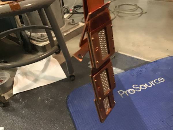
| 1600 | Put stripline buckle over ends of the three striplines |
| |  |
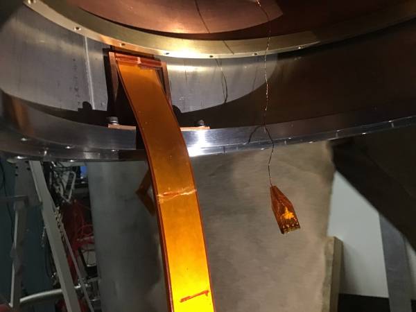
| 1610 | Attach plates to ends of the three striplines |
| |  |
| 1615 | Attach stripline elbow to upper edge of IVC lip with two screws+washers |
| | 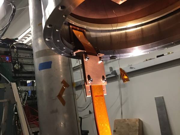 |
| 1625 | Attach lower stripline heatsink to striplines, then attach stripline heatsink to bottom of IVC lip with two screws+washers. Note: striplines are hanging lower than before as evidenced by the Sharpie marks, not sure why, possibly concerning - the stripline guides are meant to keep them clear of the 100mK can so they don't touch it, hopefully they're not touching at the top. |
| 1640 | Clean upper o-ring surface of bottom IVC section. Put new 1.5mm diam indium o-ring on bottom IVC section. Attach IVC with two screws first, being very careful not to scratch the o-ring contact surface on the bottom of the middle IVC section. (We looped the striplines and hung them over the bottom hook of the 600mK rod.) Then put in the rest of the screws and tighten all the way around several times. |
| 1650 | Start pumping out IVC with Scroll pump |
| 1655 | IVC is below 0.1 mbar, switch to Turbo pump |
| 1705 | Turbo on IVC = 1.4 ubar |
| 1720 | Turbo on IVC = 0.86 ubar |
| 1725 | Pump on IVC with Leak Detector. With Turbo still pumping, signal is less than 2 pbarL/s - very low. Valve out Turbo, LD on IVC settles around 6 pbarL/s |
| 1730 | Squirt helium around stripline elbow. No increase in leak signal! Awesome. Also squirt around all 4 indium seals, no leak seen. Squirt around T-pipe KF connections next to stripline elbow - no leak. |