2021/03/01 (Monday)
- Lab in-person: Matt
- Virtual partner: Derek, Zach
| Status | Run 74 in progress. |
|---|---|
| Setup: DIB1/2+acc → SL 41/43 → 3.2 MHz filters → cables 2/3 → nothing/motor_board+HV_board → DCRC50(3)/55(1). No lead/poly shield. | |
| 0930 | MB = 32.5 % |
| 1025 | Tower = 96.0 mK |
| 1028 | Start 31min series of -7V data (bias applied after 1 min), with 1000 beginning randoms, trigger threshold 40/40/40/40 on DCRC3qI/qO/DCRC1qI/qO, 5 Hz in-run randoms, with 1.6384 ms pulses (8192 length) and 400 us prepulse (500 length). Use sequence r74_takeandflash_dcrcbias.msl |
| 1037 | Started out triggering constantly. DCRC3 thresholds are OK but DCRC1 thresholds had to be increased drastically. Finally settled on DCRC3qI/qO/DCRC1qI/qO = 40/40/400/1600. |
| 1100 | Checked toward the end of the sequence and it was triggering constantly again. |
Here's a look at some of what we're seeing in the data recently:
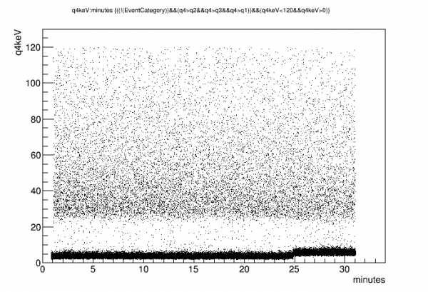 |
| This is the center channel. I'm using the approximate absolute calibration that Nick derived for Run 67. No peak near 60keV is visible. There is also no change in amplitude versus time as was seen in Run 67. |
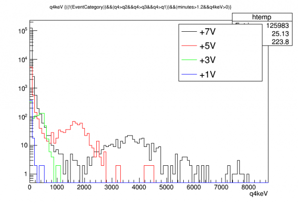 |
| Here's the high-energy spectrum using Nick's calibrations over a range of positive biases. We can see the muon bulge energy is dependent on bias - apparently charge collection efficiency drops strongly as the bias is decreased from 7V to 1V. It would be interesting to increase the bias again and see if CCE continues to rise. At any rate this suggests biasing is working correctly. One thing to wonder about is whether the Side2 electrode is properly grounded - might it be floating? If so then you might expect a weaker field across the detector… |
| 1315 | Matt enters lab, attends group meeting |
|---|---|
| 1420 | Get Kurt Wick's Co-57 source from Kevin Booth in Tate, transport it to PAN 43 |
| Let's test the idea that the Side2 electrode is not properly grounded. Question: if we connect the cable for DIB2+acc directly to the DCRC, leaving off the diverter boards, will this present any problems? Looking at the interposer wiring diagram, we see that all accessories - motor coils, endstops, Side2 electrode - are connected to QET returns. So, plugging the cable directly into the DCRC should connect those all to analog ground. That should be fine for test purposes. |
|
| 1430 | Tower/MC/Coldplate = 94.8/31.1/187 mK, Still = 1.44 K / 0.130 mbar / 0 mW, G1/G2= 194/168 mbar, 1K Pot = 1.68 K / 36±2 mbar. |
| 1435 | On ODB set all QET biases to 0. |
| 1455 | Turn off DAQ programs. Power down DCRC55(1). Disconnect diverter boards. Connect Cable 3 directly to DCRC55(1). Power up DCRC55(1). Turn on DAQ programs. Note - as usual lately, DAQ programs would not come on at first try, had to disable DCRC3, then turn them on and back off, then reenable DCRC3, then they came on. |
| OK, we can try taking data in this configuration and see whether it looks different. But I need to start the LHe transfer. So, I'll go ahead and start a series, and it will run for a while until the transfer starts. We'll try the triggers at threshold=60. | |
| 1459 | Start 31min series of 7V data (bias applied after 1 min), with 1000 beginning randoms, trigger threshold 60/60/60/60 on DCRC3qI/qO/DCRC1qI/qO, 5 Hz in-run randoms, with 1.6384 ms pulses (8192 length) and 400 us prepulse (500 length). Use sequence r74_takeandflash_dcrcbias.msl |
| 1515 | DCRCs were overtriggering, so spent a while messing with thresholds, finally settled on DCRC3qI/qO/DCRC1qI/qO = 300/50/2750/1300. Also turned off the 5Hz randoms. |
| 1532 | Begin LHe transfer @ MB = 21.6% |
| 1607 | Finish LHe transfer, MB = 90.0% |
| 1735 | MB = 89.8% |