2017/09/14 (Thursday)
| 1130 | Continue tower installation |
|---|---|
| 1315 | 100 mK stage is finished, 4K shield in place. Ready to install SQUETs. |
| note: SQUET ZC13 was damaged on August 30. pA SQUID and Feedback lines are broken, and (apparently) one LED line is broken. SQUID and Feedback aren't relevant to this run. DIB1 has no working DIB LEDs, so we'll use ZC13 on DIB1. | |
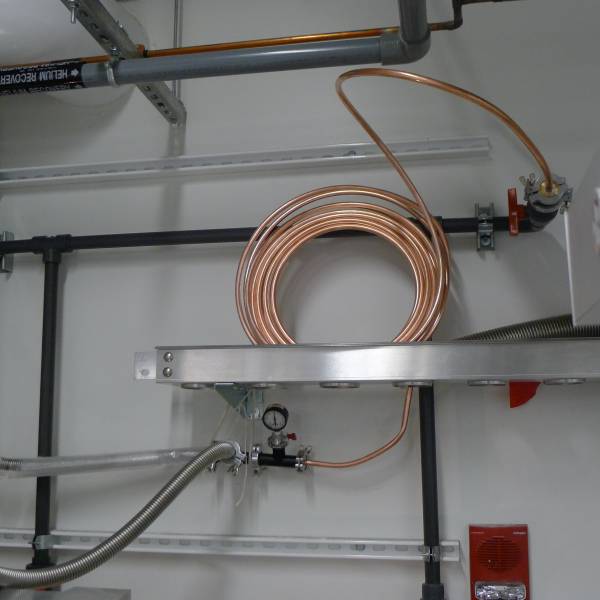
| 1315 | Attach copper warming tube to our He recovery system. |
| 1433 | Complete DIB1 room temp electrical check. Looks good! |
|---|---|
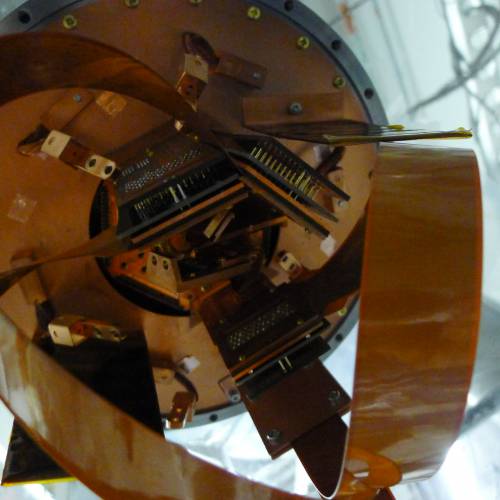
| 1455 | Plug SQUETs into DIBs 3,4. It's pretty crowded, but hopefully will work. |
| 1520 | During DIB3 checkout we discovered the electrode LEDs are probably connected wrong. They are connected to QET bias lines, but these lines route through the signal coil in the SQUID card. These coils add 10-20 kΩ at room temperature and no diode voltage is seen. While they should superconduct at base, the impedance may cause problems with running the LEDs. On 2016 Sep 1 Nick discovered that some SQUETs are wired opposite to others in terms of which line is QET bias and which is QET return, so maybe we can swap out the SQUET for one wired in the opposite way. |
|---|
- The electrode LEDs are wired to even-numbered pins 2,4,6,8 on DIB3. These are typically labeled QET Bias
- On standard SQUETs, the even-numbered tower-side QET pins connect directly to the signal coil. Odd-numbered pins do not connect to the coil but lead through to the return wire.
- Nick's measurements show that ZC-13 and ZC-26 are non-standard SQUETs
- Currently ZC-26 is connected to DIB4 and ZC-37 is connected to DIB3
- So if we swap ZC-26 to DIB3 and ZC-37 to DIB4, we should wind up with the DIB3 electrode LEDs not routed through the signal coils, and they'll work normally.
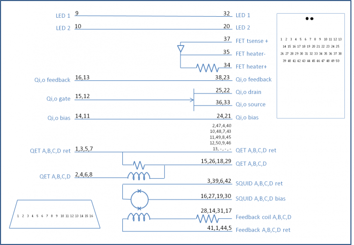 |
| SQUET pin diagram for standard SQUETs. For non-standard SQUETs the two QET labels on the left (tower-side) are reversed. |