2017/02/06 (Monday)
| Setup: DIB1/3/4 → 3.2 MHz filters → cables → nothing/DCRC55(1)/nothing | |
| 0910 | Tower/MC/Coldplate = 36.4/30.8/186 mK, Still = 1.1 K / 0.110 mbar, G1/G2 = 170/170 mbar, 1K Pot = 1.693 K / 30 mbar, Main bath = 67.5%. Boil off rate: |
| 0915 | Fill LN2 cold trap bath. |
| 0945 | IbIs on DIB3pB (DCRC1) in the normal region with varied front-end gain. (Driver gain = 2x.) The question is whether it is more linear at different front-end gains. |
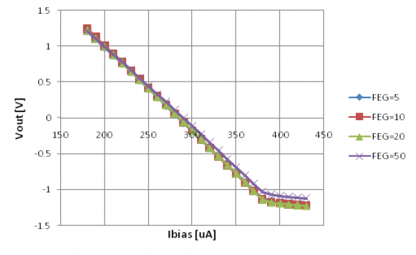 | 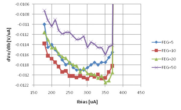 |
| As before we see the slope changes at Ibias>380 μA for no clear reason. | Front-end gain 10 has a flattish part from 250-350, but at greater gains it starts to slope the other way. |
It's also of note that the overall slope is significantly shifted in the FEG=50 case (implying higher Rnormal), but this was after a relock. “270+” was accidentally entered as QETbias which caused a railing, then a significantly different driver offset. I decided to try relocking the SQUID (set Polarity to Open and then back to non-inverting). Then the driver offset was back around where it was before. But the IbIs curve slope had changed. Before the relock it was about the same as the FEF=5 and FEG=20 cases. So does relocking significantly change the normal part of the curve??
At the higher front-end gains, which are probably more accurate, the slope-versus-bias trend is pretty linear, suggesting a quadratic shape.
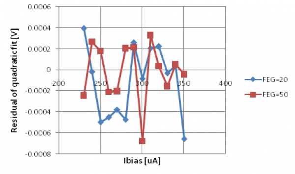 |
| This plot shows the residuals after a quadratic fit for the two highest front-end gains. In the FEG=20 case there is still a residual shape but in the FEG=50 case the residual is featureless suggesting a very good fit. However the random error seems greater at FEG=50, not surprising due to the strong high-freq oscillations. The fit range was restricted to 230-350 μA |
| 1228 | Taking stock of all DCRCs. Will try DCRC32 and DCRCX on DIB1. |
|---|---|
| 1235 | Power up DCRCX on DIB1 with appropriate ODB settings. |
| 1250 | |
| 1308 | Zap DIB1 SQUIDs |
| 1342 | Able to connect test signals to all phonon channels. Using DIB1 squid settings, are able to see pulses on all 4 channels. DCRCX looks good! |
| 1347 | Power down DCRCX. Plug DCRC32 into DIB1 and power it up. The temp immediately begins to rise. Telnet session shows 15V power is off (rd 30 = 0100) do “wr 30 0900” then “wr 30 0800” to turn on 15V power and then turn off FET heater. Temperature starts to fall. |
| 1357 | Tower temp seems stuck at 139 mK |
| 1359 | DCRC32 still seems responsive to telnet session. Start up MIDAS programs with DCRC5 (DCRC32) enabled. Can see phonon noise traces in SQUID tuning gui, so at least they're talking |
| 1403 | Trying to connect test signal to FB lines using SQUID tuning gui, but it does not seem to “take”. The gui does not show record the change and the trace seems unaffected. The gui does seem to allow connection of the test signal to QET lines, though it has not been confirmed if this is really happening. |
| 1410 | Changing ODB settings “ DCRC5 / Phonon / TestSignalConnect ” from 'n' to 'y' freezes gui. Restarting gui does not seem to help. DCRC still responds to telnet. |
| 1415 | Restarting MIDAS DCRC programs lets us bring the SQUID tuning gui back to life. |
| 1417 | Changing ODB settings “ DCRC5 / TestSignal / ConnectTestToQET ” freezes gui again. |
| 1423 | Restart DCRC ODB programs, traces recovered. Let's just set the SQUIDs blind and try to see some pulses. |
| 1424 | Zap DIB1 SQUIDs. At this temperature (140 mK) can't tell if anything happened. |
| 1427 | Changes to PA QET bias have no effect on baseline. |
| 1429 | While changing QET bias in DCRC control gui, pulse viewer again freezes. Shut down DCRC programs and power down DCRC32. |
| 1506 | Repower DCRC32, turn on 15V power at telnet session. Again, tower temp plateaus at 140 mK |
| DCRC | Rev | Issues |
|---|---|---|
| 1 (SN 55) | C.1 | |
| 2 (SN 33) | C.0 | No test signal |
| 3 (SN 50) | C.1 | Flatlines all channels spontaneously at intermediate voltage value |
| 4 (SN X) | C.1 | Lore tells of test signal and noise problems, but this is not currently observed. |
| 5 (SN 32) | C.0 | A history of power, connectivity and noise issues all using external POE box. |
| 1510 | It looks like DCRCX can be used to replace the failing DCRC50. Setup: DIB1/3/4 → 3.2 MHz filters → cables → DCRC55(1)/DCRC33(2)/DCRCX(4) Set DCRC1 as timing master. |
|---|---|
| 1515 | Tower temp rises to 300mK, begins to settle back to base temp. |
| 1519 | Turning on DCRC ODB programs. dcrc_driver01: okay! , towerfe3_01: okay! , triggerfe2: immediately crashes dcrc_driver01 |
| 1523 | Change DCRC4 / General / TriggerSource from test signal to threshold to match other slave boards. Start DCRC programs, they seem to run okay for a few minutes, but then dcrc_driver01 and towerfe3_01 crashed spontaneously. [image not archived: facepalm.svg] Oops, still had DCRC5 enabled in ODB. |
| 1539 | Start up ODB programs, all DCRCs seem to be responding. Let's tune DIB4's SQUIDs. |
| SQUID settings so far this run | ||
|---|---|---|
| Channel | SQUID Bias (uA) | Lockpoint (mV) |
| DIB1 pA | -91.2 | -4.3 |
| DIB1 pB | -78.8 | -3.3 |
| DIB1 pC | -82.0 | -4.8 |
| DIB1 pD | -85.2 | -2.7 |
| DIB3 pA | -54.0 | -1.8 |
| DIB3 pB | -60.3 | -1.8 |
| DIB3 pC | -46.3 | -2.0 |
| DIB3 pD | N/A | N/A |
| DIB4 pA | ||
| DIB4 pB | ||
| DIB4 pC | ||
| DIB4 pD | -56.0 | -5.4 |
| 1613 | Tuning DIB4 PC SQUIDs - all DIB4 (DCRC4) phonon channels flatlined at -0.2684 V. Charge flatlined at -0.2126 V. Channels on other DCRCs seem fine. Shut down DCRC programs and power cycle DCRC4. |
|---|---|
| 1620 | After power cycling DCRC4, all DIB4 phonon channels flatlined at -0.3355 V. (Charge still flatlined at -0.2126 V). Shut down DCRC programs again and power cycle DCRC4 a second time. |
| 1624 | After power cycling DCRC4 for 2 minutes, it seems to be working fine for now. |
| 1640 | After zapping, all DIB4 (DCRC) phonon channels flatlined at -0.181 V. Charge flatlined at -0.1448 V. |
| 1649 | Shut down DCRC programs. DCRC4 ended the telnet session but we could reinitiate the session and communicate with it via telnet. Restarted DCRC programs, could communicate with DCRC4 but all phonon channels still flatlined . |
| 1703 | Fill LN2 cold trap full. |
|---|