2012/02/06
| 0935 | Filled LN2 cold trap partially (missing ~1L). |
|---|---|
| 1229 | Filled LN2 cold trap fully. New dewar in gas tank room! |
| 1905 | A few matters to consider with regards to the problems witnessed with the interface boards on Saturday: |
- Traces from DCRC33 were practically non-existant. Every now and then there a very sharp negative trace would appear in Qi & Qo.
- Jeter suggested turning on the FET heater. We tried this during the afternoon, but with no success. However, turning on DCRC32's FET heater seemed to do the trick… not sure I understand why.
- Phonon channels B, C or D on DCRC33 railed. Probably nothing to worry about, but why do we see noisy traces on DCRC33 phonon channel A and all phonon channels on DCRC32?
- Traces from DCRC32 were very noisy. Every now and then one could see pulses in Qi & Qo.
- Pulses from DCRC32 and DCRC33 are still noisy. Tried to place copper sheet between interface boards, but this didn't seem to solve the problem. May have to extend shielding on DCRC boards and keep playing around. At the moment, the level of noise is far too high to take any good quality data.
- Tower temperature started rising steadily as bias was applied. Not sure why. Seemed to possibly reach a plateau at just over 90 mK.
- Vuk suggested that this might be a loading problem of some sort. Perhaps this might have something to do with the noise issue above.
- Potential between QET A return and Qi/Qo was 10% of applied bias. Resistance across crystal should be in GΩ region, so the phonon pins should be the points of highest potential. Maybe there is something I've forgotten to consider. Could try replacing R38 with 10 MΩ resistor, but shouldn't have to!
- Jeter pointed out that the multimeter would have an input impedance of around 10 MΩ. A quick glance at the manual reveals that this is indeed the case. With the above in mind, we should see around 10% of the true potential across the crystal when measuring with the Fluke 177 DMM.
- Could not flash LEDs on DCRC33 while interface boards were plugged in. LEDs on DCRC32 were fine. Could this have something to do with the fact that DCRC33 was the master board? Need to take a hard, long look at the circuit diagrams.
- Seems to work now. This appears to have been related to point 1 above.
| 1825 | Fill N2 cold trap full. |
|---|---|
| 1955 | Took some noise data at 0 V bias with interface boards installed (07120206_1950). Random trigger event rate started at 6 Hz, increased to 10-12 Hz, then decreased to around 1 Hz after about 300 events. It stabilised at around 1 Hz for the remainder of the run. Not sure why… |
| 2025 | Remove interface boards and plug DCRC boards back in. |
| Took some noise data at 0 V bias without interface boards (07120206_2025). Everything looked fine. | |
| Start flashing detector. | |
| 2055 | Stop flashing detector. |
| 2140 | DCRC33 yielded negative pulses when taking -2 V bias data. Stopped data acquisition, cycled power on board and reset timing link. Flashed detector for 15 s. Waiting for cooldown. |
| 2230 | Start taking data, four half-hour data series at each bias: -2 V, -4 V & -6 V. Trigger threshold 40 ADC bins, trigger on Q1, 2 & 3. Not triggering on Q4 may help improve statistics. |
Random Trigger Pulses
| With Interface & DCRC Boards | DCRC only | |
|---|---|---|
| DCRC32 | 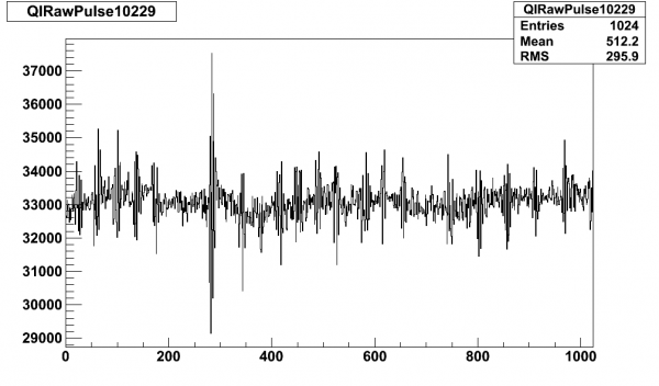 | 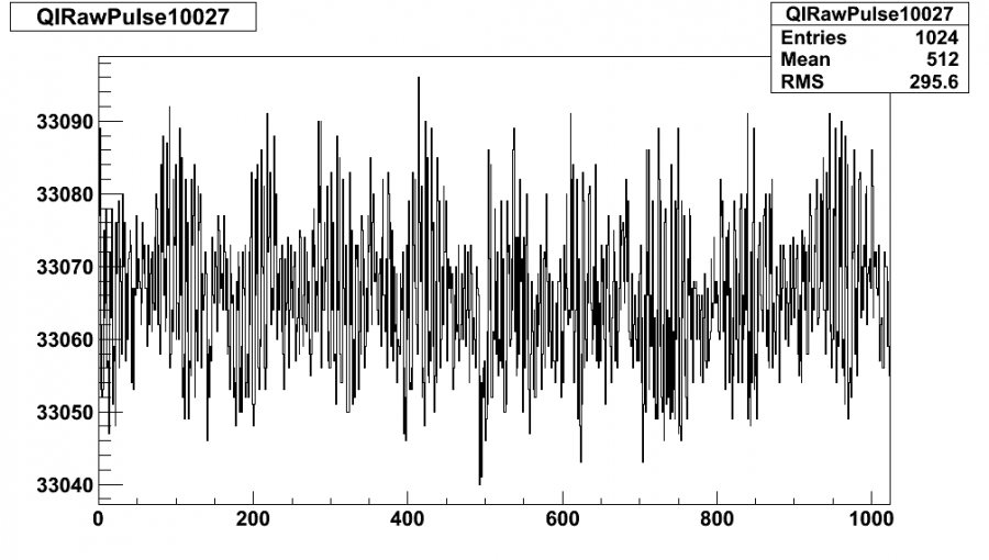 |
| DCRC32 | 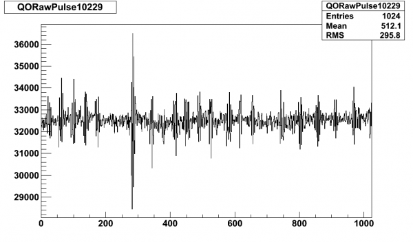 | 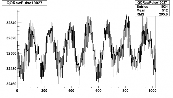 |
| DCRC33 | 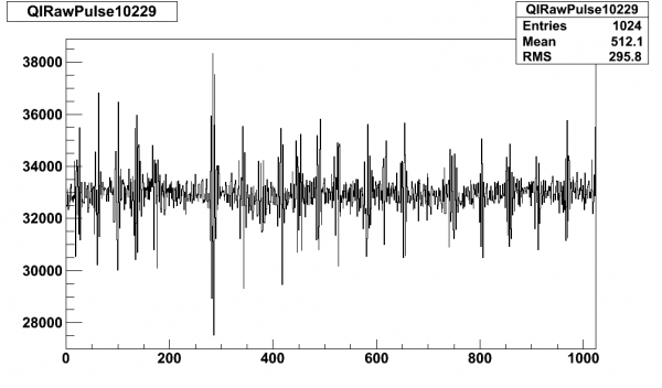 | 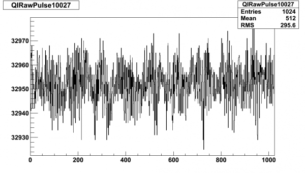 |
| DCRC33 | 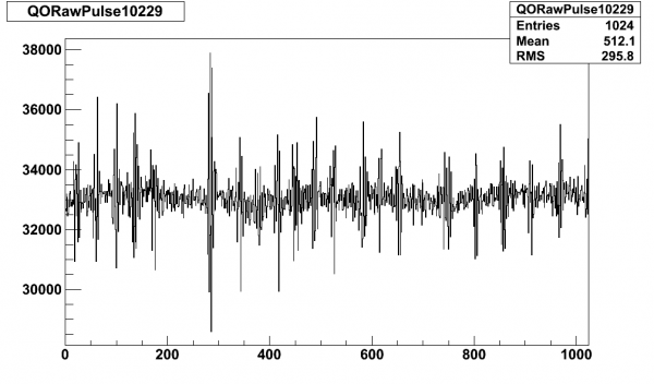 | 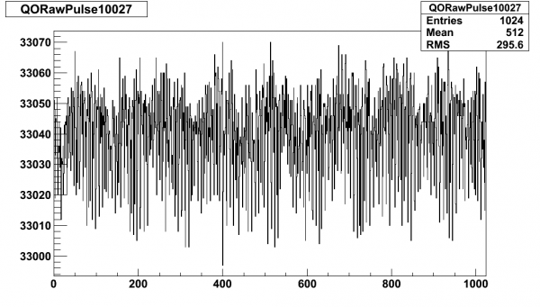 |
| DCRC32 | 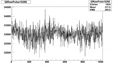 | 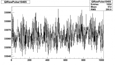 |
| DCRC32 | 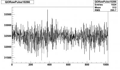 | 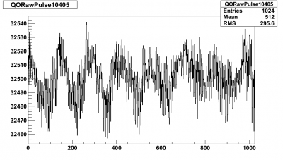 |
| DCRC33 | 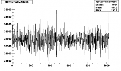 | 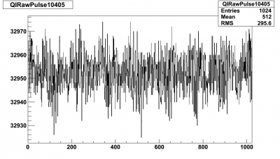 |
| DCRC33 | 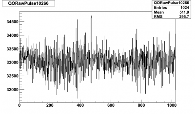 | 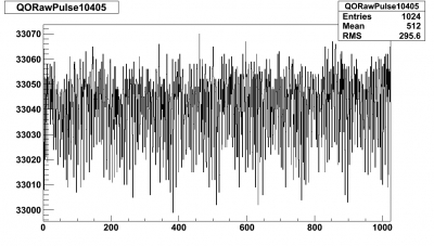 |
| With Interface & DCRC Boards | |
|---|---|
| DCRC32 | 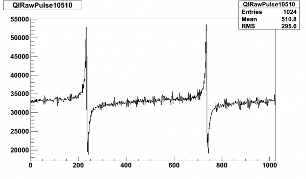 |
| DCRC32 | 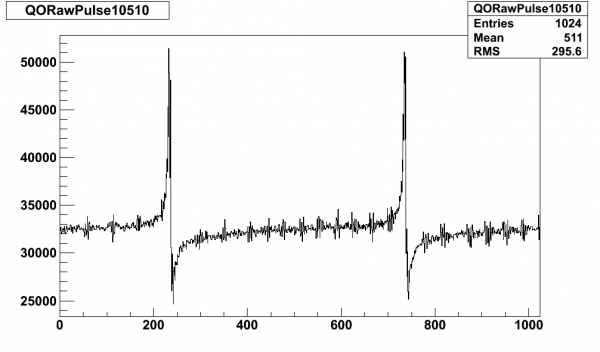 |
| DCRC33 | 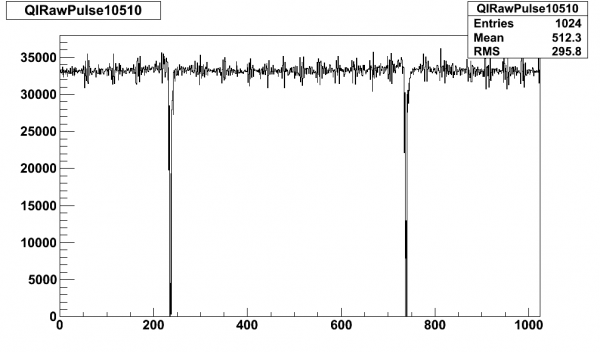 |
| DCRC33 | 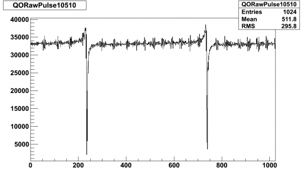 |