Table of Contents
Run 71 Charge Calibration
First Pass
The charge channels can be calibrated absolutely based on the charge amplifier circuit. The voltage signal generated at the first amplifier stage is set by the charge induced at the feedback resistor/capacitor, Q_FB, and the feedback capacitance, C_FB, as $V=Q_{ind}/C_{FB}$. Neglecting any stray capacitance to ground or between charge electrodes, Q_FB will be the same as the charge induced at the coupling capacitor, which will be the same as that at the measurement electrode according to the Ramo theorem. Capacitances amongst the detector electrodes and to ground can tend to reduce the fraction of induced charge at the feedback resistor by up to ~20%, but measuring this is not simple and is neglected here.
We don't measure the feedback capacitance directly (in fact, there is no feedback capacitor per se, this is just the capacitance of the feedback resistor itself) but we can determine it from the pulse fall time. The charge pulse fall time is $\tau_{fall} = R_{FB}*C_{FB}$ and we measure the feedback resistances during electrical checks.
Here are the measured values for this run:
TString qnames[]={"QIS1","QOS1","QIS2","QOS2"}
double Tfall[]={39.7, 39.0, 39.5, 37.6}//Pulse fall time in [us]
//Pulse fall time = R_FB*C_FB
double R_FB[]={1/20e-9, 1/20e-9, 1/21e-9, 1/22e-9}//[Ohm] From cooldown electrical check
There is also a factor due to built-in amplification in the DCRC amplifier stages. This factor is 4.0(5.5) for DCRC RevC(C.1). There is a factor to convert from ADC to volts, which is 1V / 16000ADC. And also a polarity factor depending on the charge bias direction. Finally, there is a factor converting from Coulombs to keV, which, for Ge is 3.8e-3 keV /1.6e-19 C.
Putting these all together, we get that the Calibration factor from ADC to keV is:
VperADC*C_FB/DCRC_gain/Capcitance_gain_factor/electron_charge*(keV/eh pair)
For this run, these factors turn out to be:
double G[4]={0.21429, 0.210511, 0.307822, 0.306969}
Here is an example of how to use these in an alias to provide absolute charge calibration:
//Absolute calibration to energy of event measured by channel
//+/- bias
z->SetAlias("QIS1keV","QIS1OFnoXvolts*QIS1norm*0.21429");
z->SetAlias("QOS1keV","QOS1OFnoXvolts*QOS1norm*0.210511");
z->SetAlias("QIS2keV","QIS2OFnoXvolts*QIS2norm*0.307822");
z->SetAlias("QOS2keV","QOS2OFnoXvolts*QOS2norm*0.306969");
//-/+ bias
z->SetAlias("QIS1keV","-QIS1OFnoXvolts*QIS1norm*0.21429");
z->SetAlias("QOS1keV","-QOS1OFnoXvolts*QOS1norm*0.210511");
z->SetAlias("QIS2keV","-QIS2OFnoXvolts*QIS2norm*0.307822");
z->SetAlias("QOS2keV","-QOS2OFnoXvolts*QOS2norm*0.306969");
Capacitance Corrections (In progress)
As discussed above, stray capacitances will reduce the fraction of signal seen at the amplifier. The challenge is in determining what those stray values are. This note on the iZIP v6 mentions “Capacitance per face estimated at 167 pF, suggests ionization noise sigma degraded 10% to 445 eV.”
As discussed in the R65 Crosstalk Analysis, the combination of capacitances gives an effective gain of
Gcap = C_coupling/(C_coupling+C_ground+C_otherChannels)
The coupling capacitor specs are 300 pF, so with the extra ~167/2 pF per channel, (presumably due to interleaved phonon channels), and capacitance to ground of >40pF (P.Brink) we get reduction be a factor of Gcap = 300/(300+167/2+40) = 0.71. However, in the R71 data, this factor appears to be more like 0.85. We can perform our own capacitance measurements on the detector in it's housing to nail these values down better.
G106a Capacitance Measurements
The primary capacitive coupling in the iZIP v6 is between the interleaved charge and phonon channels on the same face, as well as between each channel and ground. The QO electrode overlaps primarily with PA while QI is interleaved with the other phonon channels. These capacitances are shown in the figure below, where C_xy indicates the capacitance between channel x and y, where A,B,C,… represents PA, PB, PC, … and I,O represents QI, QO.
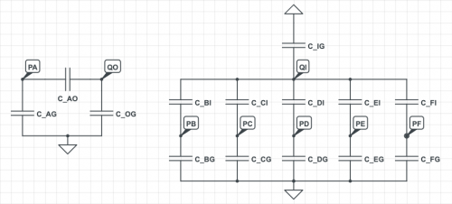 |
| Capacitive coupling amongst phonon, charge, and ground. |
|---|
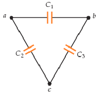
In general, a phonon channel is coupled to a charge channel and both are coupled to ground. This is a triangle of capacitors as in the diagram below. Any measurement made across one of these capacitors will also see the other two.
 |
The capacitances themselves can be inferred from the measurements as:
TODO