Table of Contents
R71 Phonon Collection Efficiency
Before/After Motor Operation
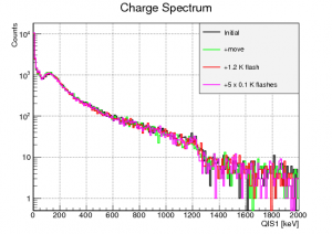
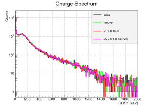
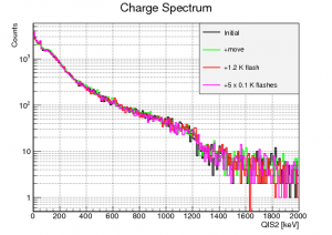
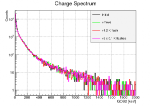
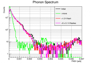
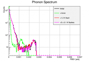
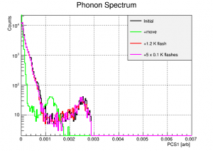
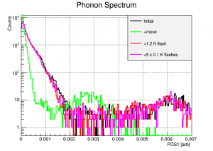
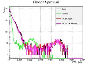
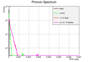
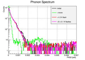
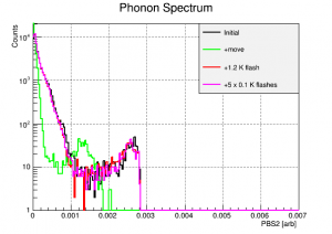
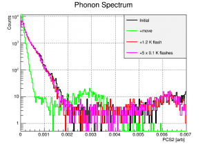
It was discovered that, after each operation of the motor, the phonon collection efficiency (PCE) of the QETs was diminished. We believe this to be a result of the superconducting Al fins trapping magnetic flux from the motor drive coils. After operating the motor, we observed reduced PCE on all channels, but unchanged charge collection efficiency. This indicates lower PCE at the fin/QET level.
| Charge spectra with move and flash | |
|---|---|
| QIS1 | QOS1 |
 |  |
| QIS2 | QOS2 |
 |  |
| Phonon spectra with move and flash | ||
|---|---|---|
| PAS1 | PBS1 | PCS1 |
 |  |  |
| PDS1 | PES1 | PFS1 |
 |  |  |
| PAS2 | PBS2 | PCS2 |
 |  |  |
| PDS2 | PES2 | PFS2 |
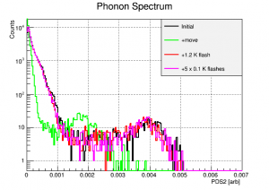 | 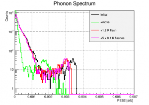 | 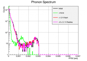 |
The reduction factors for these channels are as follows:
| Channel | Reduction Factor | Uncertainty |
|---|---|---|
| PAS1 | 3.70 | 0.12 |
| PBS1 | 3.68 | 0.16 |
| PCS1 | 3.65 | 0.17 |
| PDS1 | 3.72 | 0.13 |
| PES1 | 3.85 | 0.1 |
| PFS1 | 3.68 | 0.14 |
| PAS2 | 3.94 | 0.09 |
| PBS2 | 3.60 | 0.13 |
| PCS2 | 3.67 | 0.1 |
| PDS2 | 3.41 | 0.11 |
| PES2 | 3.78 | 0.11 |
| PFS2 | 3.66 | 0.15 |
Mean = 3.70, Stdev = 0.13
There are no clear trends in these factors either in detector face or channel proximity to the motor. The heating and flux trapping must be similar throughout the whole detector housing.
We were able to restore the PCE by heating the detector above 1.2 K, the Al SC temperature, for a few seconds using LEDs installed inside the detector housing. This procedure restored the PCE. Further flashing didn't change this.
PCE Stability
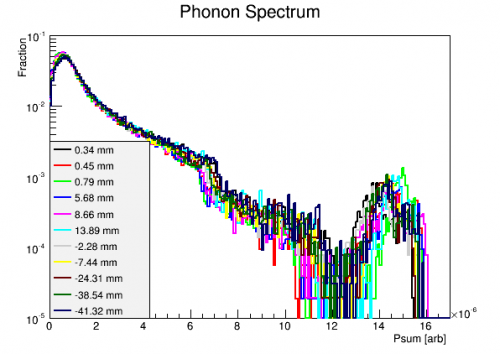
To evaluate PCE stability and repeatability throughout the run, we analyzed the summed phonon spectrum at each source location. The Psum quantity was constructed using the phonon relative calibrations. The stability of this spectrum indicates that the PCE was consistently restored after each round of motor operation.
| Summed Phonon Spectra throughout the run |
|---|
 |
Comparison to R54
The same detector (G106a) was operated in R54. We tried to compare the phonon signals in R54 and R71 to determine if the presence of the motor reduced PCE. The source configurations of the two runs were different. R54 had the Pb source plate on detector side 1 with the 241-Am located out near DIB2 (PES1, PDS1). In R71, the source mover was on side 2 and position “R”, at a radius of 38.5 mm was similar to that of R54. Another difference was that R54 had the cryostat Pb and poly shield in place, while R71 did not. This means that we can't just compare the overall spectra as above.
We instead compared the individual channel integrals (P*INTall) for the 60keV events. The average of P*INTall for charge-symmetric, 60 keV events was calculated for each series. The ratio of the R71 signals to the R54 signals is shown below:
| 60 keV Signal Ratios | |
|---|---|
| Channel | R71/R54 INTall ratio |
| PAS1 | 1.72 |
| PBS1 | 1.03 |
| PCS1 | 0.898 |
| PDS1 | 2.42 |
| PES1 | 1.30 |
| PFS1 | 0.903 |
| PAS2 | 1.84 |
| PBS2 | 0.801 |
| PCS2 | 2.20 |
| PDS2 | 1.08 |
| PES2 | 1.14 |
| PFS2 | 0.769 |
| Average | 1.34 |
Average is 1.46. So it doesn't seem like the average PCE has decreased, if anything it's higher. But there are certainly some outliers here that are not simply explained by the source being on the opposite face. The SQUET and QET bias settings were not the same in these two runs. This could explain some of the variation. One likely possibility is that the RevC DCRC, which was DCRC2 in R54, had a different gain setting due to the difference between how DAQDAQ and MIDAS work. In particular, those channels on that DCRC all have ratios in the table above around ~2. If we divide out another factor of 2 from those channels, we get the following:
| Channel | DCRC | Additional Gain factor | Adjust RevC down by x2 |
|---|---|---|---|
| PAS1 | 2 | 2 | 0.860 |
| PBS1 | 1 | 1 | 1.03 |
| PCS1 | 1 | 1 | 0.898 |
| PDS1 | 2 | 2 | 1.21 |
| PES1 | 3 | 1 | 1.30 |
| PFS1 | 1 | 1 | 0.903 |
| PAS2 | 2 | 2 | 0.920 |
| PBS2 | 3 | 1 | 0.801 |
| PCS2 | 2 | 2 | 1.100 |
| PDS2 | 1 | 1 | 1.08 |
| PES2 | 3 | 1 | 1.14 |
| PFS2 | 3 | 1 | 0.769 |
| Average | 1.00 |
It would take some more sleuthing to confirm if this is the result of old DAQ bugs, but it seems possible. At any rate, even the earlier table indicates there is no systematic shift in phonon signals between the two series. This is good evidence that the presence of the motor (and its static B field) does not reduce PCE.