R71 Motor Heating
We saw more heating than predicted when running the stepper motor. The motor was constructed similar to that described in the Porter paper, which reported heat loads of 20-50 uW when operated at a rate of 0.1-0.4 steps/sec at a drive current of 60 mA. One important difference was the type of NbTi wire which the motor coils were wound with. The Porter work used copper-clad NbTi which resulted in a coil normal resistance of 300 Ω, while our test used older, Formvar coated wire, which resulted in a coil normal resistance of ~1.7 kΩ.
The motor coil circuit(s) is quite simple, with the coil in series with the stripline (and tower wiring) resistance as well as a trim-pot (95.4 Ω on Coil A) and driven by the motor controller board with a bipolar current source. The coil resistance is 0 Ω (1.7 kΩ) when SC (normal). To monitor the motor drive signals, we monitored the voltage drop across the trim pot (V_trim) and the full loop (V_tot).
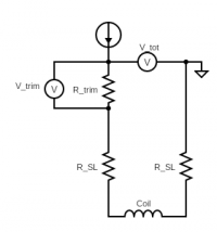 |
| Figure 1: Motor coil circuit. |
|---|
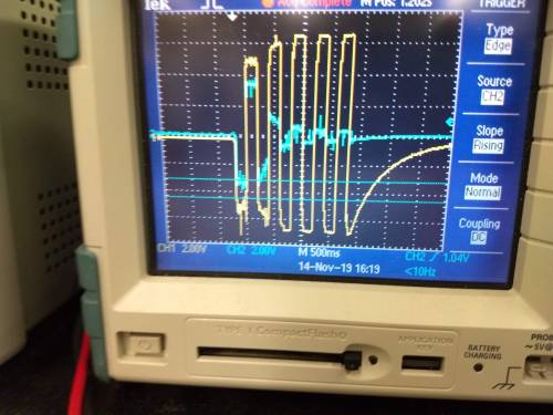
We initially tried operating the motor at a variety of dwell (time between step) settings and with improved transient control (smoothing capacitors across the coils) in attempts to reduce heating from eddy currents. One such test (Fig. 2) demonstrated the motor drive circuit was able to provide current for the first few steps, but then had to increase the drive voltage (V_tot) even as the current fell (I=V_trim/R_trim), implying an increasing resistance in the fridge. After a few steps, the drive voltage saturated due to the power supply limit. The interpretation was that some part of the NbTi motor coil was going normal.
 |
To further quantify this heating, a study of heating with constant DC current bias was performed on 2019/11/15. This showed that, even with drive currents of 2.5 mA (~10x lower than the minimum to drive the motor), the total resistance increased by 11.2 Ω. Furthermore, the tower heating observed was consistent with the resulting Joule heating (8.9 uW) being deposited at the MC stage.
The total normal coil resistance (900 turns @ 1.5–1.75 cm diameter) is 7.1–7.5 kΩ. To add this ~10 Ω, we'd only need to drive L_coil*10 Ω / R_coil = 6.4±0.7 cm of the NbTi normal (~10 K). This is less than 2 turns of it.
The critical current of these wires should be on the order of 1 A, so there must be some other local heating that warms the NbTi coil. Two possible sources are the resistance of the wiring harness (~8“ of Cu wire) connecting the motor coil to the top of the tower, or the joint between this harness and the NbTi. This joint was formed by entwining the stripped end of NbTi with the Cu strands, soldering this, then heat-shrinking the assembly. To avoid damaging the thin NbTi during handling, this joint was packed into the motor housing with the coils.
Measurements of a small test segment of NbTi connected to two pieces of normal wire in the same manner as in the motor assembly, estimate that each such joint could be as high as 2.7±0.7 Ω. (This resistance is difficult to estimate as the normal resistance of a small segment of the NbTi is estimated from the total length and resistance of the motor coils.)
The volume of NbTi we're talking about driving normal in the 2.5 mA DC test is 4 cm * π * (0.002”)² = 3.24×10^-4 cm^3. Using a density of 6000 kg/m^3 gives a mass of ~2 mg (about that of a mosquito apparently). The specific heat of NbTi is around 1 mJ/g/K, so the heat to warm 2 mg of NbTi to T_C ~ 10 K is ~20 uJ. Using the estimate of Joule heating above, this could occur in just a few seconds if the heat-sinking of the wiring harness and NbTi-harness joints are poor. It is harder to estimate the heat deposited when the much higher stepper motor drive current is used as it could only be operated for a few hundred ms before heating drove the drive currents to 0.
Based on the results above, we conclude that the combination of high normal resistance, poor heat sinking, and inefficient connection to the NbTi are likely contributing to the unstable, runaway heating observed in this run. Future improvements to the motor setup should try to address these issues, possibly through use of different varieties of NbTi, better wiring heat-sinking, and a superconducting wiring harness.