2019/11/14 (Thursday)
| Setup | DIB1/2/4 → 3.2 MHz filters → cable 1/2/3 → gender changer 1/2/3 → movable source controller/board with external Feedback resistor/nothing → DCRC55(1)/DCRC33(2)/DCRC50(3) |
|---|---|
| 0904 | Tower/MC/Coldplate = 35.1/30.4/193 mK, Still = 1.52 K/ 0.130 mbar / 0 mW, G1/G2= 216/193 mbar, 1K Pot = 1.65 K / 30±2 mbar. MB= 70.5% |
| 0908 | Fill LN2 cold trap bath. |
| 0933 | Power arduino and connect to it via telnet. Then turn on the motor controller power supply to 8V. Set the dwell to 8 ms. Set the current step position with wr currstep 500. Oscilloscope is connected across both the motor coils to monitor voltage. |
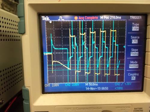
| 0936 | Move to step 650 with command mvto 650. Tower spikes to 1.74 K. The signal on coil A (yellow trace) is a series of 4-6V square pulses and on coil B (blue trace) there are similar pulses but not nearly as clean. Disconnect from and power down arduino and motor power supply. |
 |
| 0940 | Tower = 301 mK |
|---|---|
| 1237 | Tower = 35.6 mK |
| 1240 | Power arduino and connect to it via telnet. Then turn on the motor controller power supply to 8V. Set the dwell to 8 ms. Set the current step position with wr currstep 650. Oscilloscope is connected across both the motor coils to monitor voltage. |
| 1241 | Move to step 792 with command mvto 792. Tower spikes to 1.61 K. Leave arduino setup powered. |
| 1244 | Tower = 363 mK |
| 1245 | Check resistance between endstop lines and ground, all are open. |
| 1310 | Re-arrange oscilloscope probes so that chan 1 is monitoring voltage across coil A and wiring inside the fridge (not including trim pot) and chan 2 is monitoring voltage across the trim pot. Currently, resistance of trim pot A = 37 Ohm and coilA + fridge wiring = 137 Ohm. Further checking reveals we didn't quite have this set up as we thought. Chan 2 was measuring the voltage across the coil ignoring the trim pot while chan 1 included everything. |
| 1313 | Power arduino and connect to it via telnet. Then turn on the motor controller power supply to 8V. Set the dwell to 8 ms. Set the current step position with wr currstep 792. |
| 1314 | Move an additional 10 steps to 802 with command mv +10. Tower spikes to 800 mK. Endstop resistances are open. |
| 1327 | Power down arduino stuff and DCRC1 to adjust some probe wiring. |
| 1340 | Re-arrange oscilloscope wiring probes so chan 1 is monitoring everything (trim pot + motor wiring) = 132 Ohm, consistent with previous set up. Chan 2 is monitoring only the trim pot = 95.5 ohms. |
| 1345 | Power arduino and connect to it via telnet. Then turn on the motor controller power supply to 8V. Set the dwell to 8 ms. Set the current step position with wr currstep 802. |
| 1348 | Move an additional 20 steps to 822 with command mv +20. Tower spikes to 950 mK. Endstop resistances are open. |
Okay, this is easier to interpret. The yellow curve is output voltage of the motor driver and blue is voltage across the trim pot, so it's proportional to drive current, I_D as I_D = V_trim/R_trim. This indicates the drive current starts at ~50 mA but falls to ~10 mA after ~20 steps. Testing with the warm motor showed min I_D ~ 48 mA. It seems like the coil resistance starts increasing as soon as we send a signal, and the motor driver can't source enough current, so we're probably not stepping more than a few steps each time.
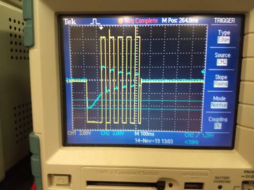
| 1657 | We suspect that eddy currents from the sudden changes in motor drive current are causing most of this heating. Bench tests with the warm motor showed that the addition of 200 uF capacitors in parallel with the motor coils smooths these changes with a time constant of ~25 ms. Set up this same circuit with the cold motor using a breadboard. |
|---|
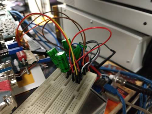
| 1703 | Power on Arduino, adjust power supply to 8 V, connect to Arduino via telnet, set dwell to 50. |
|---|---|
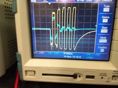
| 1704 | Move an additional 20 steps to 842 with command mv +20. Tower spikes to 1.165 K. Endstop resistances are open. |
It looks like the first few steps required lower total voltage and the current signal remains flat. So maybe the slower rise times are letting the coil stay SC longer.
| 1720 | Tower = 63 mK |
|---|---|
| 1721 | Try increasing dwell again to 100. |
| 1722 | Move an additional 20 steps to 862 with command mv +20. Tower spikes to 1.4 K. Endstop resistances are open. |
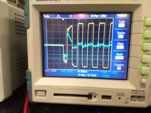
Blurry photo, but the current signal went down by the 2nd step, so the longer dwell didn't quite help.
| 1726 | Fill LN2 cold trap full. |
|---|---|
| 1910 | Tower = 36.0 mK Dang, forgot to power DCRC1 back on, can't take data overnight. |