2022/12/26 (Monday)
- Lab in-personnel: Matt
| Status | Run 76 finished |
|---|---|
| Setup | DCRC33(2)→HV control, NaI trigger signal → DCRCX(4) |
| IVC closed and Turbo pumping for a few days. No tower - this is just a leak test. | |
| 1450 | Turbo on IVC = 4.0 nbar. With Turbo valved out for 1 minute, IVC = 54 nbar. |
| 1515 | Pump IVC with leak checker, Turbo valved out. Baseline 2.20 pbarL/s, slowly creeping up during measurements. Squirt He around stripline elbow, KF joints near stripline elbow, all four indium seals. No significant increase in leak signal. Throughout tests LD increases from 2.20 to 2.29 pbarL/s. So if there's a leak it's less than 0.1 pbarL/s. |
| Thinking about the broken Tower wires on face 6 and what to do about them | |
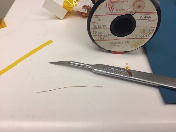
| Had considered using the Cu-clad NbTi that we used for the motor coils to replace the Tower wires. But Cu is a bad choice if you want low thermal conductivity. The Tower wires are similar to the motor wires. The motor wires are 0.079 mm diam not including insulation, c/w Tower 0.066 mm. The Tower wires are heatsunk to copper pads on three PCBs at the LHe, Still, and MC stages. Between the stages the copper has been etched away leaving thermally-insulating NbTi. An alternative is manganin, often used for cryogenic applications when you want a low heat leak. We have a spool of 0.006“ diameter manganin. Plots from Pobel suggest the thermal conductivity is proportional to T: mu=CT, where C=0.04 W/m/K2. Then power between two temperatures is P = 0.5*C*A/L*(T_hi2 - T_lo2), with A the cross-sectional area and L the length. The separation between the Still and MC PCBs is 1.8 cm, and if we assume the temperatures are 1.0 K and 30 mK, for 8 wires this gives a heat leak of 0.16 uW. Probably acceptable. |
|
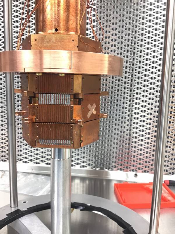
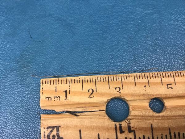
| 1605 | Remove all three cover plates from the Tower Face 6. As it turns out, the wire breaks are all between 4K and Still. Between Still and MC all wires are still continuous. So we only need to replace the wires from 4K to Still. The total length including the solder pads is 5.3 cm. The length between solder pads is 3.4 cm. Cut a piece of manganin and scrape insulation off the ends, about 5 mm, with scalpel. Takes a lot of time to tin the ends with solder, doesn't stick well to manganin. |
 |
|
 |
|
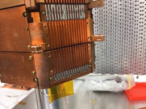
| 1620 | Remove old wire from Pin 1. While pulling the upper piece, I almost peeled it completely away from the Still solder pad. Got to avoid this. Instead I cut it at that pad. Was able to solder one end of the manganin at the top (Still) pad. But I left it too long really for the bottom. Cut some away at the bottom and scraped off insulation, tried to solder but hard to hold it down. Came up with another idea… |
| 1645 | Cut a piece of manganin, 0.5+3.4+1.0 cm long. Scrape off 0.5 mm at one end - this will be top (Still) side. Scrape other end starting at 3.4 cm from where the insulation is removed on the first end - don't really need to remove it all the way down. The idea is to solder the top, then tape down the free end against the bottom of the tower then solder the bottom, then remove the tape and trim the wire at the bottom. |
| 1650 | Actually managed to solder a piece on Pin1 and get continuity. However I also produced a short to chassis. Removed the wire and cleaned up some slopped solder at the PCBs. Will need to be careful about shorts and check at each stage. |
 |
|
 |
|
| 1735 | With LD on IVC pretty stable at 6.0±0.3 pbarL/s, do a couple more He squirts at stripline elbow. Signal doesn't budge. |