| Status | Run 76 prep. All mixture in dump. LHe Trap and LN2 Trap 1 still have contaminants. Cryostat Vacuum Jacket pumped out. Tower removed. |
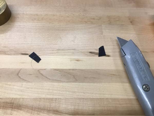
| 1115 | Practice trimming insulation off the Cu-clad NbTi wire. I use a box cutter and I taped the wire to the table with black electrical tape and carefully scraped off insulation from ~5mm of the end. Then untape, turn wire over, scrape opposite side. Ohmmeter check looks good. |
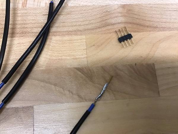
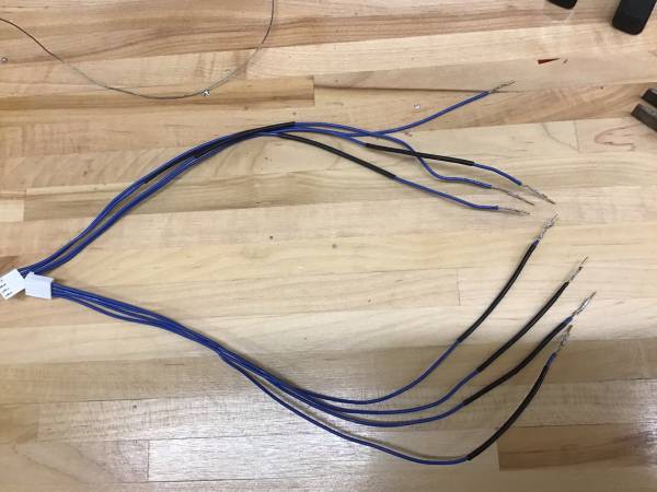
| 1115 | Start soldering MillMax pins to the ends of the wires on the connectors to the 2D Source Mover controller. We can plug these in one-by-one to the new connectors that will be on the motor wires. |
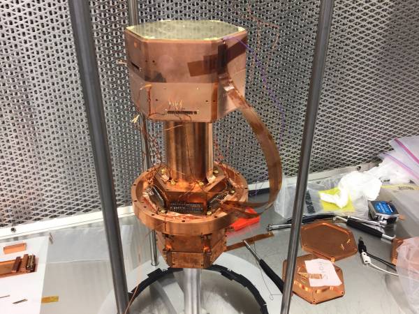
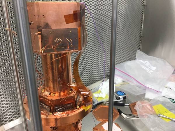
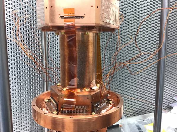
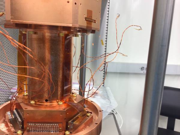
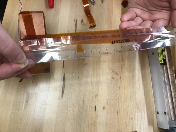
| 1125 | Take 2D source mover to tower in cleanroom and do a fit test of the striplines. They are inconveniently long, we were too conservative making sure they wouldn't be too short. |
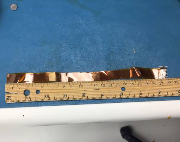
| 1205 | Make a dummy stripline with some Kapton tape and a connector to work out the optimal length, so there's the right amount of slack to tape the striplines down against the tower spool. From the end of the kapton stripline at the housing to the end of the pins of the connector should ideally be about 22 cm. |
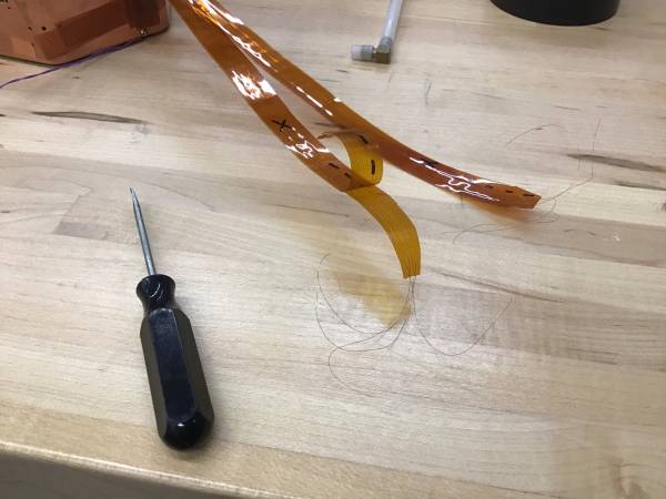
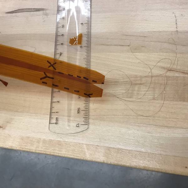
| 1225 | Peal back Kapton on the 2D source mover striplines to reduce the length. Could shove tweezers between the pieces of Kapton near where a wire comes out and gently pull them apart enough to then pull back with my fingers. Then cut off on the side that the wires aren't stuck to, then pull the wires off that side and cut off the other piece, than stick them back together. |
| 1310 | Finish soldering MillMax pin/sockets to ends of wires of connectors to 2D source mover controller. Redid some later to make them neater. |
| 1310 | Finished trimming the Kapton at the ends of the striplines for the 2D source mover wires. Still need to cut the wires to the proper length for soldering and strip them. |
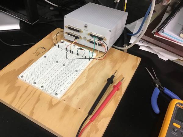
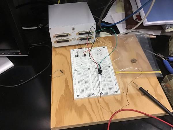
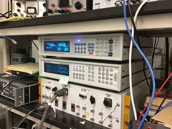
| 1455 | Set up two test resistors on a breadboard and plugged them into the LakeShore scanner to test the scanner. At first the readings were nonsensical due to an error: the two sensor connectors on the cable connecting the bridge to the scanner need to plug into the corresponding V or I plug on both sides. These were swapped originally - putting them in the right order resulted in sensible and stable resistance values. Looks good - can manually switch between channels or set it up to scan through them. |
| 1650 | Practiced soldering piece of NbTi to a pin. Concluded that my light stripping with the box cutter probably isn't good enough, solder wouldn't stick to wire. Got much better results after using sandpaper to strip it, once each on opposite sides of the wire end. |