| Status | Run 75 finished. All mixture in dump. LHe Trap and LN2 Trap 1 still have contaminants. Cryostat Vacuum Jacket pumped out. Tower removed. |
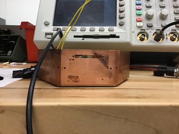
| 1400 | Bring S104 to wirebonder lab to investigate problems with Side1pF |
| | Checked Side1pF at the DIB: around 440 Ohm (forgot to write it down but it was 400-something. A check done before Run75 was 442 Ohm.) |
| | Used a hypodermic needle as a multimeter probe to touch various pads on the detector. DIB Socket 1 DIB Pad 1 is for example a couple of Ohm. |
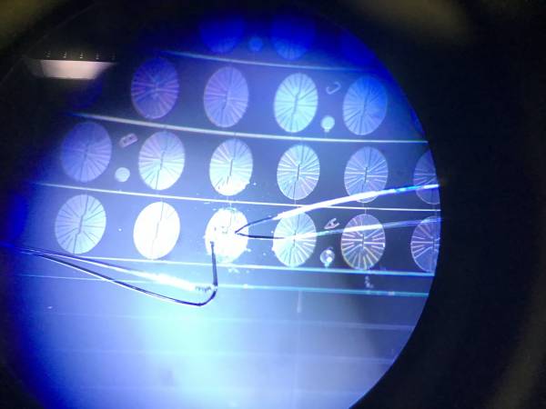
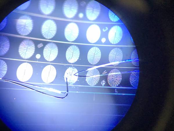
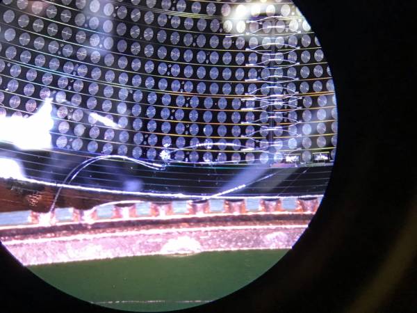
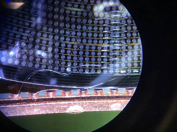
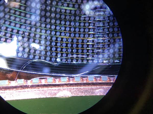
| | Noticed that the hopscotch pad that had been created by isolating a pA stadium had the two bonds connected on opposite sides of the pad… |
| | DIB Socket 1 to hopscotch pad resistance depends - if probe close to the bond to the DIB (on the left), around 4 Ohm, but if it's close to the bond on the right (to the pF connection pad), it's more like 60 Ohm. It seems like maybe that's just the resistance through the room-temperature tungsten TES. But maybe there's enough damage to the stadium that there's actually no metal continuity between the two sides, and the 60 Ohm seen is really just continuity through the silicon (which becomes open at sub-K). From DIB Socket 1 to the pF pad is 66 Ohm. |
| | Traced the pF leads for a while, measured resistance from DIB socket 1 to various pads, looked reasonable (200-something Ohm). |
| | Decided to try replacing the hopscotch-to-pF-pad bond, connecting it on the hopscotch pad closer to the other bond (presumably on the same aluminum fin). |
| | Removed hopscotch-to-pF-pad bond. With this removed, Side1pF at DIB reads 62 kOhm, much higher. |
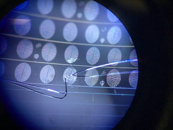
| | Made a new wirebond from hopscotch to pF pad, this time with the hopscotch bond closer to the other one, on the left side. |
| | Wirebonder settings: power = 500/500, bond time = 40/40, rise/drop = 60/30. |
| | After rewirebonding, at DIB Side1pF = 378 Ohm. So about 60 Ohm less - good. Maybe it's fixed now (though of course hard to know really) |