2022/02/01 (Tuesday)
- Lab in-personnel: Matt
| Status | Run 75 in progress |
|---|---|
| Setup | Tower Faces 5/3/2 → Cables 2/1/3 → nothing/diverter_board/nothing → DCRC55(1)/DCRC50(3)/DCRCx(4) Lead shield in place. Am Source y = 0.03 mm |
| 1350 | Goldman/Tower/MC(H35)/Coldplate = 41.4/72.5/34.0/182 mK, Still = 1.40 K / 0.110 mbar / 0 mW, G1/G2= 266/247 mbar, 1K Pot = 1.59 K / 11±1 mbar, MB = 30.4%. |
| 1350 | Fill LN2 cold trap bath. |
Current phonon settings shown below. We'll use the same Lockpoint and SQUIDbias for each detector channel after switching to HV. And possibly the same VGAGain values for each DCRC.
[/Equipment/Tower01/Settings/DCRC1/Phonon]
VGAGain (multiplicative factor) = FLOAT[4] :
[0] 5
[1] 5
[2] 2
[3] 5
LockpointAdjust (mV) = FLOAT[4] :
[0] -3.5
[1] -3.8
[2] -4
[3] -2.5
SQUIDBias (uA) = FLOAT[4] :
[0] -80
[1] -95
[2] -91
[3] -102
QETBias (uA) = FLOAT[4] :
[0] 239.9
[1] 283.5
[2] 275.3
[3] 199.9
[/Equipment/Tower01/Settings/DCRC3/Phonon]
VGAGain (multiplicative factor) = FLOAT[4] :
[0] 5
[1] 5
[2] 5
[3] 5
LockpointAdjust (mV) = FLOAT[4] :
[0] -3
[1] -3.4
[2] -2.9
[3] -3.4
SQUIDBias (uA) = FLOAT[4] :
[0] -50
[1] -70
[2] -70
[3] -60
QETBias (uA) = FLOAT[4] :
[0] 180.6
[1] 174.6
[2] 220.1
[3] 0
[/Equipment/Tower01/Settings/DCRC4/Phonon]
VGAGain (multiplicative factor) = FLOAT[4] :
[0] 2
[1] 3
[2] 3
[3] 3
LockpointAdjust (mV) = FLOAT[4] :
[0] -4
[1] -5.4
[2] -2.3
[3] -5.7
SQUIDBias (uA) = FLOAT[4] :
[0] -70
[1] -80
[2] -70
[3] -75
QETBias (uA) = FLOAT[4] :
[0] 230.7
[1] 164.4
[2] 258.9
[3] 202.5
| DCRCs 1 and 3 were used in Run68 for HV output 1 and 2. Let's try that again. I added HV-board mapping to the table on the Run 75 summary. Looks like most of DCRC1&3's settings will be unchanged (though we can consider setting SQUID stuff to zero on unused channels, DCRC1pD and DCRC3pA). The exception is that DCRC3pB should get the SQUID settings from DCRC4pC - see below: |
Modified setting for HV board, assuming DCRCs 1&3 used:
[/Equipment/Tower01/Settings/DCRC3/Phonon]
LockpointAdjust (mV) = FLOAT[4] :
[1] -2.3
SQUIDBias (uA) = FLOAT[4] :
[1] -70
QETBias (uA) = FLOAT[4] :
[1] 258.9
| One unfortunate thing about this plan is that Side1pF will be connected to the same DCRC channel. It may be worth a test to connect that cable to a different DCRC just to verify that the problem with that channel is not DCRC related (quite unlikely). | |
| 1350 | Take a look at phonon channels - all 11 look good. Look at noise: mostly around 1e-6 from 300-1e4 Hz, or a tad lower. |
| 1355 | Turn off DAQ programs, then power down all three DCRCs. This causes a temperature spike up to 46.0 mK, then it falls again. |
| 1405 | Goldman = 39.8 mK and cooling. Coldest we've seen. So DCRCs warm tower by at least 1.6 mK… |
| 1410 | Goldman = 39.1 mK and cooling. So DCRCs warm tower by at least 2.3 mK… |
| 1415 | Goldman = 38.9 mK and cooling. So DCRCs warm tower by at least 2.5 mK… |
| 1425 | Connect Cable 1 (with accessories) → DCRC4 and adjust DCRC4pD. This way we can double-check the dead channel Side1pF. |
| 1430 | Mini-IbIs on DCRC4pD (Side1pF): scanning from QET bias = 600 to 0, output changed linearly from 0.1152 V to 0.1192 V (4 mV decrease), suggesting a very high normal resistance and no s/c transition. |
| Noticed that connecting only DCRC4 to Cable 1 only increased the temperature to 39.0 mK. | |
| 1450 | Connect Cables 2/1/3 → nothing/diverter_board+extra_board/nothing → HV CONN1/2/3. Needed the extra board on Cable 1 because otherwise the accessory board would be in the way of the next cable. |
| 1455 | Connect DCRC1/3 to HV Output 1/2. Power DCRCs. Make adjustment to DCRC3pB phonon settings as above. Configure ODB and start DAQ programs. Tower spiked to 0.2 K when the DCRCs were powered but now it's cooling. |
| 1500 | Goldman = 48.9 mK and cooling |
| 1505 | Pulses seen in all 5 working channels (DCRC1pA/B/C, DCRC3pB/C). Noise looks OK, still around 1e-6 V |
| 1510 | Goldman = 41.1 mK, good - already a little cooler than this morning. |
| 1510 | Establish timing link (DCRC1 master, DCRC3 slave) and trigger on DCRC1pA, verify timing link working. |
| 1515 | Plug Kepco 0-1000V power supply into Variac. Connect to HP meter. Set HV to 0V. Then connect to HV board voltage input. Watching DCRC1pB, no new noise, looks fine. |
| 1520 | Dial HV up to 20V. No noticeable increase in noise. |
| Let's try a little data. Obviously things aren't optimal, should maybe zap SQUIDs and we may want to flash at some point. But we'll take a look. | |
| 1530 | Goldman = 40.8 mK. Set QET biases to target dP/dI=1.0 uV and adjust driver offsets so baselines ~ -0.9 V |
| 1534 | Start +20.0 V data series, 16 min long, with 1000 initial randoms, no in-run randoms, trigger on DCRC3pC threshold 20. Start series with the Start Button. |
| 1552 | Begin LHe transfer @ MB = 27.6% |
| 1555 | Dial down HV to 0.0 V. Then connect HV leads together to ground Side2. |
| 1629 | End LHe transfer @ MB = 93.7% |
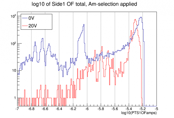
Plot above compares last 0V series to the new 20V series. In the 0V case this is the sum of Side1 OFs (surprisingly the processing doesn't seem to be doing PTS1, PTS2). The NTL gain is clearly seen. Empirically it's about 7.1; higher than expected, 1+20/3.8 = 6.3.
Measured noise width ~ 22 eV. Note this is with dead pF.