| Status | Run 74 prep. 1K Pot pumped out and isolated. Fridge and 4He and LN2 Trap 1 isolated, not pumped out. Cryostat vacuum jacket pumped out. IVC open, tower removed. |
| 1419 | Matt arrives at lab. |
| 1430 | PAN N2 supply to Physics was shut off two days ago due to unidentified leak. So our purge cabinets were no longer being purged. It was supposed to be back on today but there was no flow. Tried to follow the lines - it seems that the feed line is inside the wall so impossible to follow. Anyway, Mike Rother finally figured out a regulator valve was closed, and got it open, and flow is reestablished. I adjusted our main regulator valve to get the rates on the flowmeters around 4. |
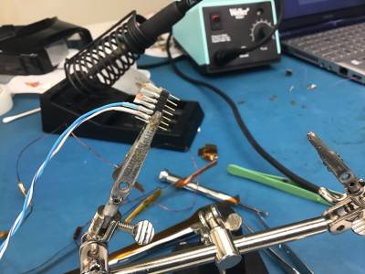
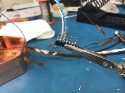
| 1500 | In clean room, remove old source mover motor connection wires from connector. Removed the shrink tube by kinda pushing it off with the soldering iron - seems that when the solder is liquid, the shrink tube can just slide off the pin. Leave the endstop wires connected.
  |
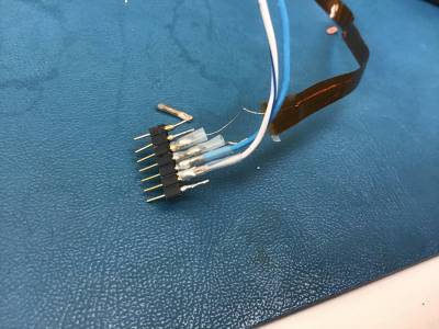
| 1520 | Solder one pair of motor wires onto connector. Trying to use shrink tube, and planning to tape wires with Kapton tape after finishing
 |
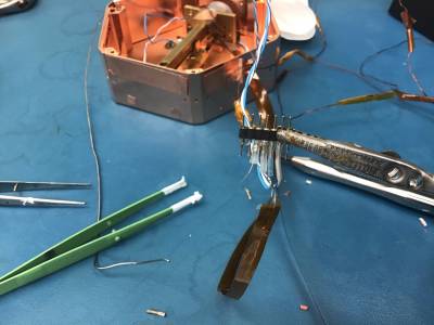
| 1530 | While manipulating connector, one of the tinned NbTi ends breaks :(
 |
| 1535 | Remove endstop wires from connector so that I can have more control to make motor wire connections more carefully. Trim down the unbroken NbTi wire; so that only several mm extends past the Kapton stripline. Then solder ends to connector pins.
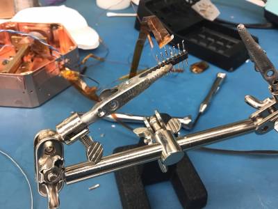 |
| 1540 | Tape over ends of NbTi and connector pins with Kapton (for insulation and for mechanical support).
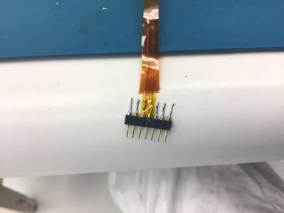 |
| 1550 | Do something similar with second motor wire stripline. Rather than trimming the wires, add more Kapton tape up to the last few mm. Then solder to connectors and add more Kapton tape, with an additional piece of tape over both coil striplines.
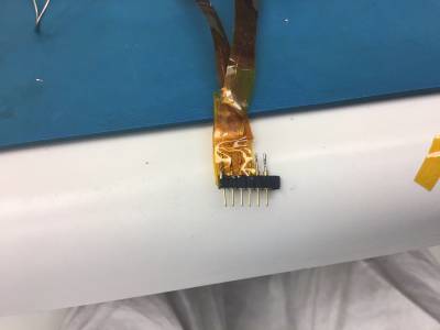 |
| 1555 | Cut connector down to only the 4 pins for the motor, again trying to protect the delicate NbTi wires.
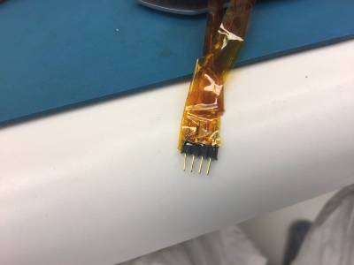 |
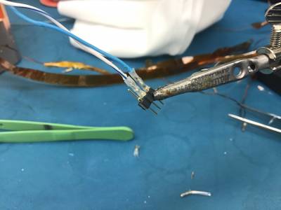
| 1605 | Solder endstop wires onto another 3-pin connector.
 |
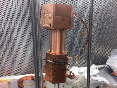
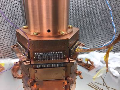
| 1615 | Check that the striplines reach the Tower connector when source housing is in second position. Looks good.
  |
| 1625 | Realize that for this run the source plate needs to be attached to the bottom of the source housing (tower side), not the top. So pull the connector wires through the DIB slot and remove the thermometer to do the switch.
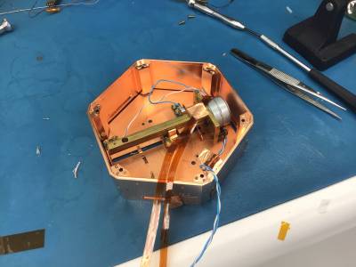 |
| 1640 | Attach source plate to bottom of source housing. Feed wires through DIB slot and reattach thermometer. One motor coil stripline is a lot longer than the other - so tape down the slack inside of the housing so that the sections coming out of the DIB slot are the same length.
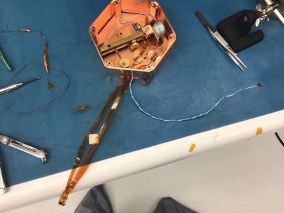 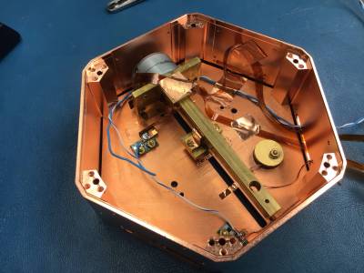 |
| 1645 | Look at the side coax extender. The current plan for doing HV wiring is to bend the pin corresponding to the Side 2 electrode on USD1 so that the pin does not connect to the Tower socket, then solder a wire to that pin that connects to the Tower face for the other accessories.
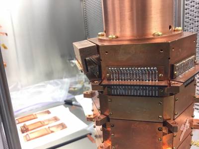 |
| 1647 | Matt leaves lab. |