2021/01/04 (Monday)
- Lab in-person: Matt
- Virtual partner: Ruiren
| Status | Run 74 prep. 1K Pot pumped out and isolated. Fridge and 4He and LN2 Trap 1 isolated, not pumped out. Cryostat vacuum jacket pumped out. IVC open, tower removed. |
|---|---|
| 1320 | Matt enters lab |
| 1325 | Prepare to trim stripline for second source mover motor coil 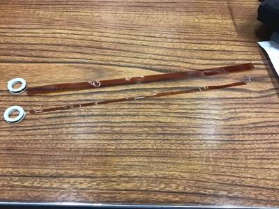 |
| 1335 | Trim stripline for second motor coil 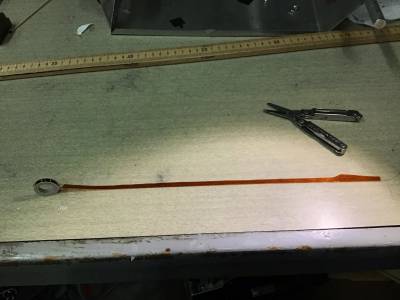 |
| 1345 | Bring motor coils into clean room 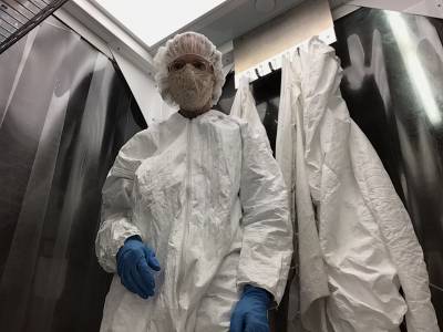 |
| 1350 | Wrap coil wire with Teflon tape 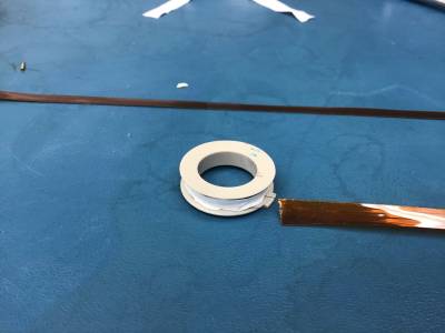 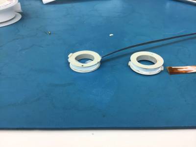 |
| 1355 | Tape coil wire down with yellow electrical tape 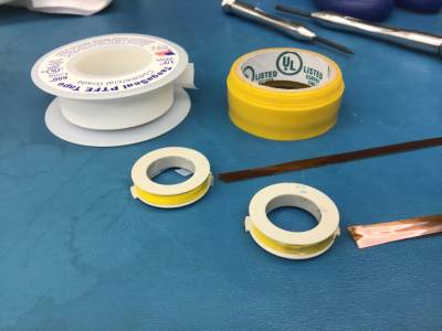 |
| 1400 | Prepare to reassemble motor 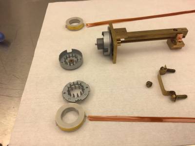 |
| 1405 | Assemble source mover pieces 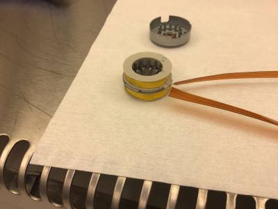 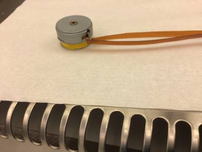 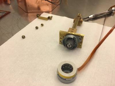 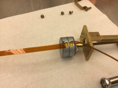 |
| 1410 | Screw motor housing onto motor mount plate 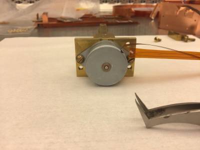 |
| 1415 | Screw motor housing strap onto motor mount plate [image not archived: img_00103.jpeg] |
| 1415 | Check coil resistances, look good 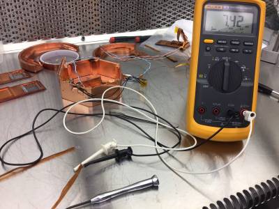 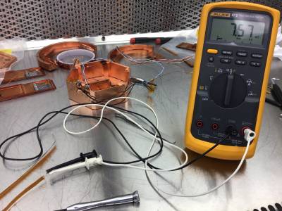 |
| 1430 | Remove screw terminal setup and external LEDs from source housing. Accidentally broke a wire off one of the LED boards. Leave endstops and thermometer in the housing. Leave the blockers as is. 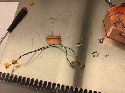 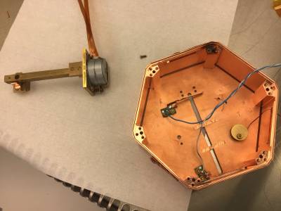 |
| 1435 | Note that motor mount plate attaches at outermost pair of holes in source housing base plate. 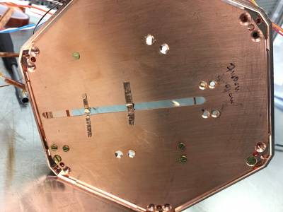 Screw motor mount plate onto base plate 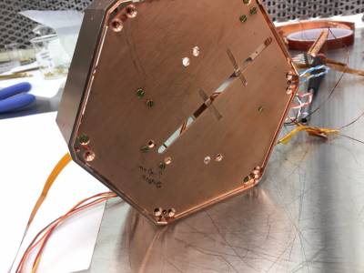 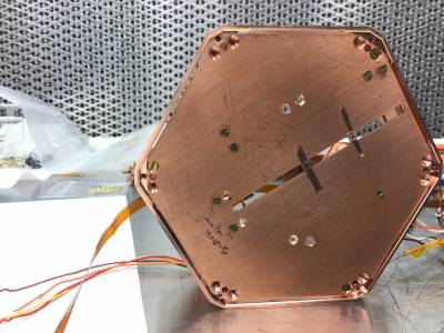 |
| 1440 | Check for shorts from coil wires to housing - none found. 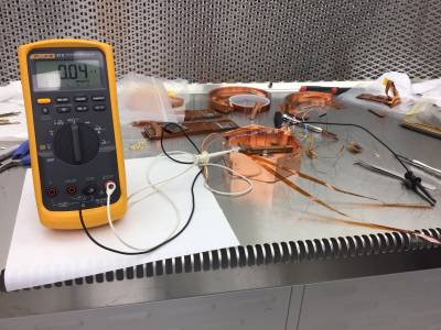 |
| 1440 | Turn shaft by hand and center source to y=0mm by eye. 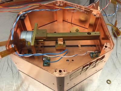 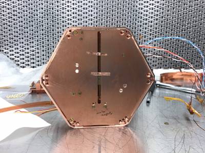 |
| 1445 | Guide coil wire striplines as well as endstop and thermometer wires through DIB slot. Then tape down with copper tape. 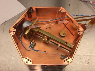 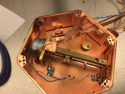 |
| 1455 | Quick electrical check of USD1, referencing 2018 Feb 26. Verify continuity between channels and ground side. 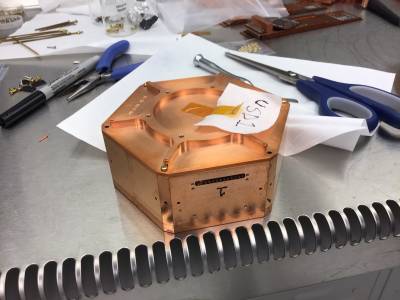 |
| 1505 | Quick check of BIAS and FEEDBACK resistances on Side Coaxes ST-3-3, ST-3-8, ST-3-10. ST-3-8 qO Bias looks open, but the other two look good. We used -3 and -8 in Run 67, maybe we'll need to try -3 and -10 this time. 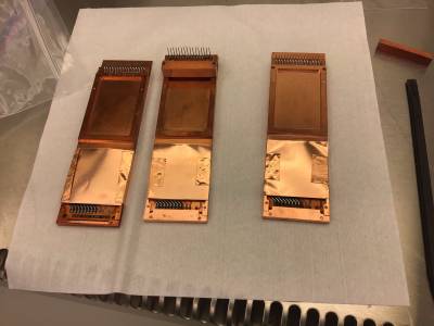 |
| 1540 | Start thinking about how we can route wiring for HV biasing… 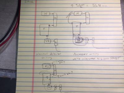 |
| 1600 | Notice that Q-Compound on top of fridge at stripline elbow is discolored and crumbly at bottom, where it repeatedly got icy and frozen during transfers. Clearly if it was ever helping with the leak, it stopped helping after a few transfers. 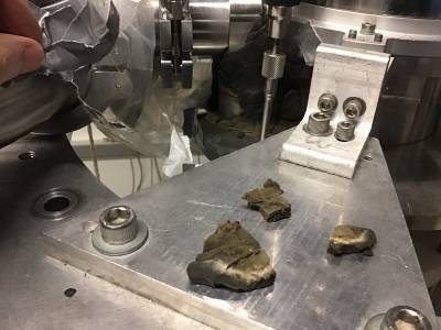 |
| 1605 | Matt exits lab |