2020/02/11 (Tuesday)
| 0935 | Check contents of warm LN2 Trap 1: 108 mbar! Well that explains why it clogged up yesterday. Pump out with scroll pump. |
|---|---|
| 0940 | Check contents of warm LN2 Trap 2: 4.3 mbar. Pump out with scroll pump. |
| 1030 | Start cryocleaning mixture through LN2 Cold Trap 1, V6 = 13.0% |
| 1050 | Increase V6 → 13.1% to speed up flow |
| 1140 | Stop cleaning through Trap 1 after 70 min. G2 flow pressure was 565-665 mbar. Pump mixture to dump. Removed 8.0 mbar. |
| 1155 | Start cryocleaning mixture through LN2 Cold Trap 2, V6 = 13.1% |
| 1205 | Increase V6 → 13.2% to speed up flow |
| 1215 | Increase V6 → 13.3% to speed up flow |
| 1300 | Stop cleaning through Trap 2 after 65 min. G2 flow pressure was 585-735 mbar. Pump mixture to dump. Removed 3.3 mbar. |
| 1315 | Check contents of warm LN2 Trap 1: 8.0 mbar. Pump out with scroll pump. |
| 1325 | Start cryocleaning mixture through LN2 Cold Trap 1, V6 = 12.7% |
| 1330 | Increase V6 → 13.0% to restart flow |
| 1345 | Increase V6 → 13.1% to restart flow |
| 1410 | Increase V6 → 13.2% to speed up flow |
| 1425 | Stop cleaning through Trap 1 after 60 min. G2 flow pressure was 570-660 mbar. Pump mixture to dump. Removed 6.1 mbar. |
| 1440 | Check contents of warm LN2 Trap 2: 3.3 mbar. Pump out with scroll pump. |
| 1455 | Start cryocleaning mixture through LN2 Cold Trap 2, V6 = 12.8% |
| 1500 | Increase V6 → 13.0% to restart flow |
| 1508 | Increase V6 → 13.1% to speed up flow |
| 1600 | Stop cleaning through Trap 2 after 65 min. G2 flow pressure was 565-605 mbar. Pump mixture to dump. Removed 2.6 mbar. |
| 1620 | Check contents of warm LN2 Trap 1: 6.1 mbar. Pump out with scroll pump. |
| 1700 | Check contents of warm LN2 Trap 1: 2.6 mbar. Pump out with scroll pump. |
| 1710 | Filled LN2 cold trap dewar. |
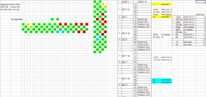
| Plan for wiring the SQUET/stripline interposer: | |
 |
|
| Actually this has some errors - some of this diagram is out of date. Corrections below: |
|
| Accessory | SQUET/Stripline pin |
|---|---|
| Coil 1a | 49 |
| Coil 1b | 50 |
| Near Endstop | 11 |
| Far Enstop | 12 |
| 1120 | Plan the stack assembly arrangement, see below: |
|---|
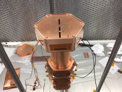 | 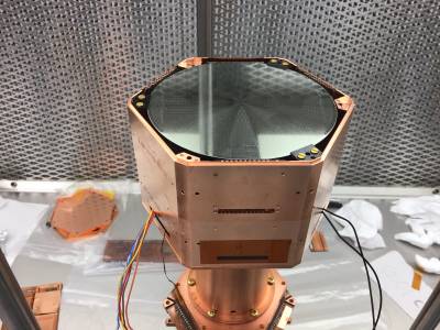 |
| The long end of the source track is oriented toward DIB1 of the detector. That means that the direction away from the motor (toward the far endstop) is in the -y direction in detector coordinates. |
|
| 1545 | Solder the two LED wires to Pins 9 and 10 of one of the side coax extenders. This will be used with the side coax for DIB4. |
|---|---|
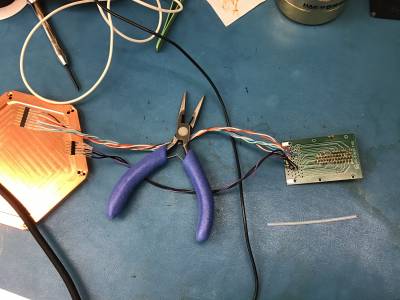
| 1615 | Finish soldering wires to the interposer board (after breaking off the appropriate sockets to bypass the SQUET). Made a second Mill-Max plug for the screw terminals and HV wires. Color-coded to match the wires to the top of the tower: thicker black wire for the screw terminals and thin purple wire for the HV wires. |