2020/02/10 (Monday)
| 0840 | Check contents of warm LN2 Trap 1: 5.9 mbar. Pump out with scroll pump. |
|---|---|
| 0840 | Check contents of warm LN2 Trap 2: accidentally started pumping it out immediately, so not sure… >3.6 mbar. Pump out with scroll pump. |
| 0855 | Start cryocleaning mixture through LN2 Cold Trap 1, V6 = 12.4% |
| 0900 | Increase V6 → 12.7% to restart flow |
| 0905 | Increase V6 → 12.8% to speed up flow |
| 0915 | Increase V6 → 12.9% to speed up flow |
| 0945 | Increase V6 → 13.0% to speed up flow |
| 1000 | Stop cleaning through Trap 1 after 65 min. G2 flow pressure was 570-585 mbar. Pump mixture to dump. Removed 8.6 mbar. |
| 1010 | Start cryocleaning mixture through LN2 Cold Trap 2, V6 = 12.8% |
| 1015 | Increase V6 → 13.0% to restart flow |
| 1025 | Increase V6 → 13.1% to restart flow |
| 1105 | Increase V6 → 13.2% to speed up flow |
| 1115 | Stop cleaning through Trap 2 after 65 min. G2 flow pressure was 560-600 mbar. Pump mixture to dump. Removed 2.6 mbar. |
| 1130 | Check contents of warm LN2 Trap 1: 8.6 mbar. Pump out with scroll pump. |
| 1145 | Start cryocleaning mixture through LN2 Cold Trap 1, V6 = 12.8% |
| 1150 | Increase V6 → 13.1% to restart flow |
| 1210 | Increase V6 → 13.3% to restart flow |
| 1250 | Stop cleaning through Trap 1 after 65 min. G2 flow pressure was 575-680 mbar. Pump mixture to dump. Removed 8.7 mbar. |
| 1305 | Check contents of warm LN2 Trap 2: 2.6 mbar. Pump out with scroll pump. |
| 1315 | Start cryocleaning mixture through LN2 Cold Trap 2, V6 = 12.8% |
| 1325 | Increase V6 → 13.2% to restart flow |
| 1335 | Increase V6 → 13.3% to increase flow |
| 1350 | Increase V6 → 13.4% to increase flow |
| 1420 | Stop cleaning through Trap 2 after 65 min. G2 flow pressure was 575-800 mbar. Pump mixture to dump. Removed 3.7 mbar. |
| 1430 | Check contents of warm LN2 Trap 1: 8.7 mbar. Pump out with scroll pump. |
| 1450 | Start cryocleaning mixture through LN2 Cold Trap 1, V6 = 12.8% |
| 1305 | Increase V6 → 13.2% to restart flow |
| 1535 | Increase V6 → 13.3% to increase flow |
| 1540 | Noticed that G2 started climbing, G1 started falling - did the trap get saturated?? G2 climbed to 1000 mbar, had to stop circulation. |
| 1545 | Stop cleaning through Trap 1 after 55 min. G2 flow pressure was 575-970 mbar. Pump mixture to dump. Removed 108 mbar. Clearly something went wrong. Should check vacuum seals around Trap 1. |
| 1555 | Refill LN2 coldtrap bath |
| 1530 | Check contents of warm LN2 Trap 2: 3.7 mbar. Pump out with scroll pump. |
| 1620 | Start cryocleaning mixture through LN2 Cold Trap 2, V6 = 13.0% |
| 1625 | Increase V6 → 13.2% to restart flow |
| 1630 | Increase V6 → 13.3% to increase flow |
| 1720 | Stop cleaning through Trap 2 after 60 min. G2 flow pressure was 570-640 mbar. Pump mixture to dump. Removed 4.3 mbar. |
| 1735 | Close off all fridge valves, remove trap 2 from cold bath so both are warming, and turn of rotary pump. |
| We have a problem with tower wiring - now that we only have the old tower, there are two bad faces, 1 and 6. There is a problem with pC on both of these - normally this would be a problem because the DIB pattern on the housing means we have to use one of these, and all 3 DIBs use pC. However: in this run we've decided to test using a twisted-wire connection on one DIB. So instead of using the corresponding tower face we can use an adjacent one instead. | |
| 0920 | Untape the NbTi wire attached to the screw terminals from the base plate. We don't want this to be well heatsunk for the purposes of the test. |
| 0930 | Remove DIBs from the former G132 housing, which we will now use for the source mover and other accessories |
| 0935 | Mount source mover/accessory plate inside of housing. Quick electrical checks of Thermometer, Source motor coils, Endstops, LEDs, and Screw terminal leads, as well as shorts to chassis. All look OK. |
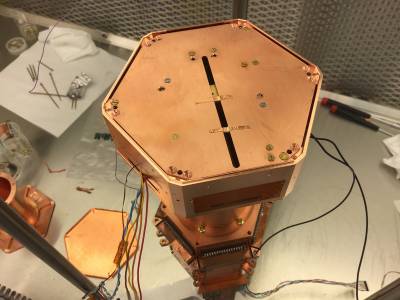
| Note that source carriage tilts a bit to left or right. Can't guarantee that it will move perfectly along a diameter of the detector. We discussed maybe tightening the clearance to the guide shaft with tape, maybe should try that. |
Accessory wiring plan: we will plug accessories (source mover, screw terminal leads, electrode) into Tower Face 4. Interposer will divert these to Face 5, which will connect to DIB4. The electrode will connect to QETA and QETA Return of the stripline corresponding to DIB4, to match the Run 70 electrode wiring.
| Tower Face 4: | |
|---|---|
| Pin | Accessory |
| 1,2 | Motor Coil 1 |
| 3,4 | Motor Coil 2 |
| 5 | Near endstop |
| 6 | Far endstop |
| 7 | (unused) |
| 8,9 | Screw terminals |
| 10 | (no connection) |
| 11,12 | HV Electrode |
We will (I think) use the interposer board from Run71, with all the source mover wiring intact. The interposer board will attach to the SQUET at Tower Face 5 (connected to DIB4). We will want to add wires for the HV - these will go to QETA and QETA_Return. We also need to add wires for the screw terminals.
| 1055 | Remove three clamps from Side 2 of G101. These clamps are in the positions of the clamps on the facing side of the electrode. This allows the two housings to mesh completely. And multimeter says that detector-to-electrode (through one phonon channel pin) still reads OPEN. NOTE: the slot in the electrode housing for the wires is arranged between DIB1 and DIB4 of the detector housing. |
|---|---|
| 1355 | Detector level checkout. Looks great! Resistances similar to before the etching. |
| Detector | G101Cmod | DIB | 1 | ||
|---|---|---|---|---|---|
| date/who: | 2020-02-10 | MF | |||
| +lead | - lead | signal | typical | previous | measured |
| 1 | 2 | QET A | 100 to 200 Ω | 114.5 Ω | 100.1 Ω |
| 3 | 4 | QET B | 100 to 200 Ω | 59.8 Ω | 58.5 Ω |
| 5 | 6 | QET C | 100 to 200 Ω | 105.0 Ω | 92.6 Ω |
| 7 | 8 | QET D | 100 to 200 Ω | open | open |
| 1-12 | chassis | <1 nS | <1 nS | <1 nS | |
| Detector | G101Cmod | DIB | 3 | ||
| date/who: | 2020-02-10 | MF | |||
| +lead | - lead | signal | typical | previous | measured |
| 1 | 2 | QET A | 100 to 200 Ω | no pin 1 | no pin 1 |
| 3 | 4 | QET B | 100 to 200 Ω | open | open |
| 5 | 6 | QET C | 100 to 200 Ω | 34.4 Ω | 36.6 Ω |
| 7 | 8 | QET D | 100 to 200 Ω | open | open |
| 1-12 | chassis | <1 nS | <1 nS | <1 nS | |
| Detector | G101Cmod | DIB | 4 | ||
| date/who: | 2020-02-10 | MF | |||
| +lead | - lead | signal | typical | previous | measured |
| 1 | 2 | QET A | 100 to 200 Ω | open | open |
| 3 | 4 | QET B | 100 to 200 Ω | open | open |
| 5 | 6 | QET C | 100 to 200 Ω | 101.0 Ω | 96.7 Ω |
| 7 | 8 | QET D | 100 to 200 Ω | 131.3 Ω | 108.8 Ω |
| 1-12 | chassis | <1 nS | <1 nS | <1 nS | |
| 1340 | Add a single layer of copper tape to each side of the source carriage bracket to narrow the clearance against the guide rod. |
|---|---|
| 1355 | Assemble stack. Then realize we don't have long enough threaded rods for three 1-inch housings. Need about 5inch long. Apparently the size of the threads is |