2020/02/05 (Wednesday)
| Mark Platt did not follow our intended wirebonding for G101, so it doesn't match our HV board wiring. The table below shows the incorrect connections in italics. However upon arrival yesterday only one channel showed continuity at the DIBs, so it seems they need rewirebonding anyway. |
| Detector channel | Intended DIB channel | Mark's DIB channel | Status | |
|---|---|---|---|---|
| TES0 (pF) | DIB4pD | DIB4pD | open | |
| TES1 (pC) | DIB4pC | DIB4pB | 106.3 Ω | |
| TES2 (pD) | DIB1pC | DIB1pD | open | |
| TES3 (pB) | DIB1pB | DIB1pC | open | |
| TES4 (pE) | DIB1pA | DIB1pA | open | pin2 connected |
| TES5 (pA) | DIB3pC | DIB3pC | open | pin5 connected |
| By Murphy's Law the one intact connection is one of the miswired ones. |
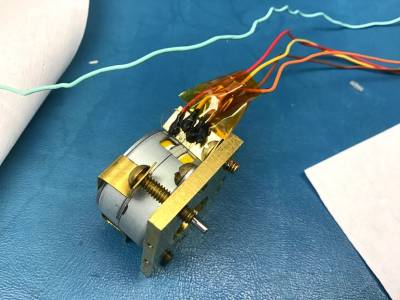
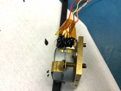
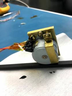
| 0955 | Check the epoxy-covered solder joints for the source mover motor wiring. The Stycast is still a little flexible, you can make dents in it with your fingernail, but it has definitely set. The two coils still read about 7 kΩ resistance. A quick check suggests that the joints are completely covered, no electrical continuity at the ends of the NbTi wires or around the Stycast. |
|---|---|
| 1015 | Take lid off G101 and examine. At first look it doesn't seem like the bonds are broken, and the detector doesn't seem shifted, because the main flat looks completely parallel with DIB1. But pushing down gently on the bonds suggests some of them have come loose from the detector pads. |
| 1025 | Check connectivity from individual pins to the detector surface. A couple of individual wires are still connected: DIB1 pin2, DIB3 pin 5 |
| 1100 | Start rebonding detector (with correct bonding scheme). Got DIB1pA and DIB1pB working after about 90 minutes. |
| bonder settings: bond1/2 power = 480/475, bond1/2 time = 40/30, loop height / drop before clamp = 50/26 mils. Later increased first bond power (DIB pad) to 485. | |
| 1230 | Reassemble motor casing to mount with brass heatsinking tab. |
| 1330 | More wirebonding. Finish DIB1 and DIB3, 4 channels done. Took about 45 minutes |
| 1430 | Finish epoxying wire joints to heatsinking tab. |
 |  |  |
| 1500 | Mounted the electrode with 3 sets of 2 20mil spacers on the electrode face side and 3 sets of 1 20mil + 1 5mil spacer on the electrode back side. |
|---|---|
| 1515 | Finish wirebonding. All 6 channels look OK. Now bonded to the intended DIB channels. Took about 20 minutes. |
| 1520 | Checked connectivity of source mover, ~40Mohm connection to ground found in brown/brown stripe wire. |
| 1550 | Rechecked connectivity of source mover, no connection to ground found this time, it must have cleared up. |
| 1600 | Attempted to measure gap between the electrode and detector. Measured a ~0.4mm gap and did not observe any connectivity between the crystal and electrode. A small piece of copper sheet was placed between them and then a connection was observed. The outer lip of the housing did not fully seal, so perhaps the screws/clamps are touching, possibly increasing the distance between the faces. |
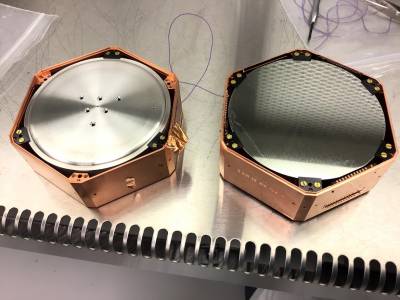 | 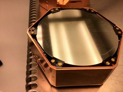 |
| Mounted electrode and etched Side 2 of G101 | another look at etched Side 2 of G101 |
| 1620 | We need a place for LEDs. Logical place is on the plate for the source mover. We need to drill a few more holes in it. |
|---|---|
| 1620 | on LED board, distance from far screw hole to LED bulb is 7 mm, screw through hole diam 1.9 mm, diam of LED bulb 1.5 mm, want a somewhat larger hole for this to poke through |