2019/10/14 (Monday)
| Status: Tower Assembly | |
| 1030 | Prepare new indium source blocker from scrap indium supply, about 1.1 mm thick. 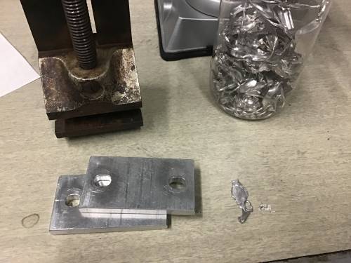 |
| 1040 | Cut strip of indium blocker to 0.125“ width to fit slot width in source plate 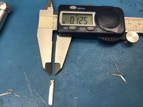 |
| 1045 | Cut indium blocker to 2.60mm length 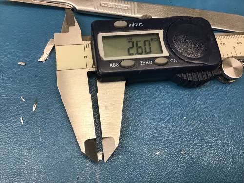 |
| 1045 | Place new blocker at nearer-to-center location, near edge at +4.59 mm from center position. 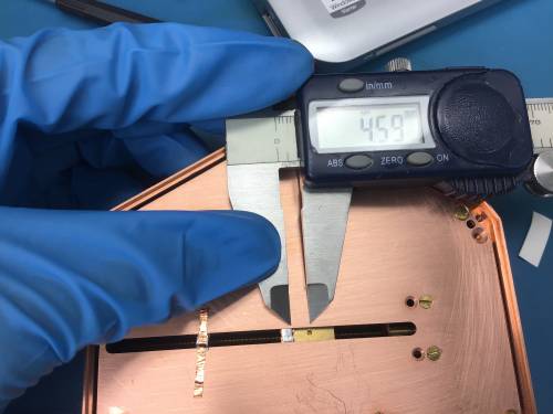 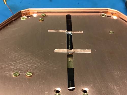 |
| Description | Distance |
|---|---|
| Center to edge of blocker 1 | 4.59 mm |
| Width of Blocker 1 | 2.60 mm |
| Center to edge of blocker 2 | 25.05 mm |
| Width of blocker 2 | 3.07 mm |
| 1055 | Put source holder on stack above detector, same orientation as Sep 17. The source will move outwards towards channel PBS2 or in the direction of DIB 2. 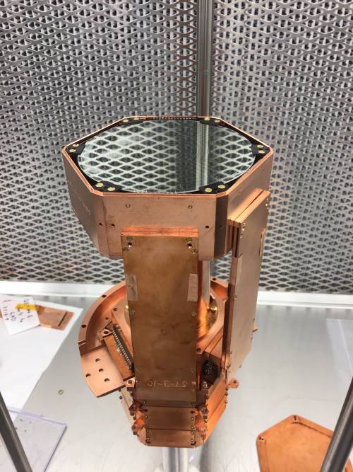 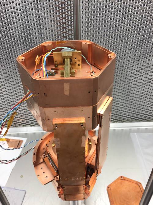 |
|---|---|
| 1100 | Tape down wires from source housing, blocking most of the light path into the source housing. 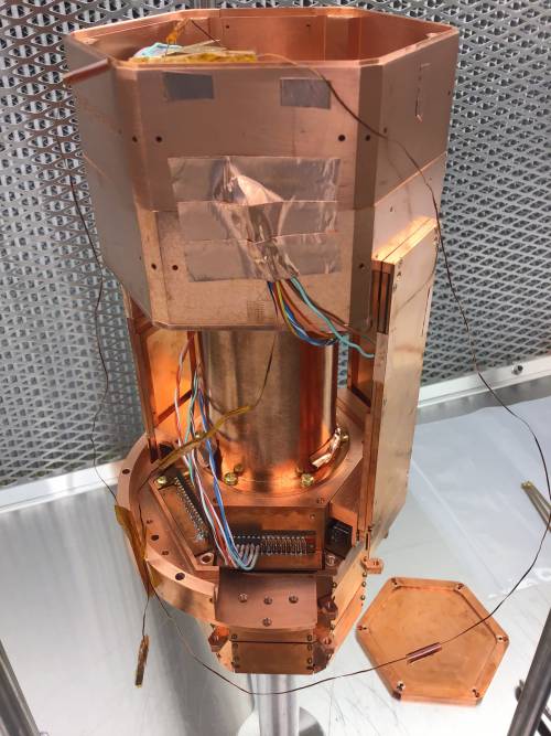 |
| Ready for electrical check. | |
| 1430 | Well, not quite ready for electrical check… take housing lid off of source holder so we can check which wire is connected to which endstop sensor |
| Detector | G106a | DIB | 1 | ||
|---|---|---|---|---|---|
| side coax | ST-3-3 | date/who: | 2019 Oct 14 | JN, MF | |
| face | 1 | ||||
| +lead | - lead | signal | typical | previous | measured |
| 1 | 2 | QET A | 100 to 200 Ω | 131Ω | 131 Ω |
| 2 | 4 | QETA-B | 100 to 200 Ω | 184Ω | 186 Ω |
| 3 | 4 | QET B | 100 to 200 Ω | 183Ω | 186 Ω |
| 4 | 6 | QETB-C | 100 to 200 Ω | 226Ω | 229 Ω |
| 5 | 6 | QET C | 100 to 200 Ω | 192Ω | 192 Ω |
| 6 | 8 | QETC-D | 100 to 200 Ω | 194Ω | 193 Ω |
| 7 | 8 | QET D | 100 to 200 Ω | 146Ω | 144 Ω |
| 2 | 8 | QETA-D | 100 to 200 Ω | 173Ω | 172 Ω |
| chassis | 9 | LED1 Rforward | 8 to 9 MΩ | 761kΩ | 1 MΩ |
| chassis | 9 | LED1 Vforward | 1.0 to 1.1 V | 1.106V | 1.10 V |
| 9 | chassis | LED1 Rreverse | <1 nS | <0.1nS | <0.1 nS |
| chassis | 10 | LED2 Vforward | 8 to 9 MΩ | open | open |
| chassis | 10 | LED2 Vforward | 1.0 to 1.1 V | open | open |
| 10 | chassis | LED2 Rreverse | <1 nS | <0.1nS | 0.1 nS |
| 1 | 11 | Qo Rbias | 24 to 26 nS | 25.4nS | 25 nS |
| 12 | 11 | Qo C coupling | <1 nS | <0.2nS | <0.1 nS |
| 12 | 13 | Qo Rfeedback | 24 to 26 nS | 25.5nS | 26 nS |
| 1 | 14 | Qi Rbias | 24 to 26 nS | 25.3nS | 26 nS |
| 15 | 14 | Qi C coupling | <1 nS | <0.1nS | 0.1 nS |
| 15 | 16 | Qi Rfeedback | 2image4 to 26 nS | 25.4nS | 26 nS |
| All pins → Ground | all <0.2 nS | ||||
| Detector | G106a | DIB | 2 | ||
|---|---|---|---|---|---|
| side coax | ST-3-10 | date/who: | 2019 Oct 14 | MF, DS | |
| face | 4 | ||||
| +lead | - lead | signal | typical | previous | measured |
| 1 | 2 | QET A | 100 to 200 Ω | 135 Ω | 206 Ω |
| 2 | 4 | QETA-B | 100 to 200 Ω | 193 Ω | 191 Ω |
| 3 | 4 | QET B | 100 to 200 Ω | 180 Ω | 135 Ω |
| 4 | 6 | QETB-C | 100 to 200 Ω | 184 Ω | 193 Ω |
| 5 | 6 | QET C | 100 to 200 Ω | 134 Ω | 180 Ω |
| 6 | 8 | QETC-D | 100 to 200 Ω | 184 Ω | 185 Ω |
| 7 | 8 | QET D | 100 to 200 Ω | 134 Ω | 134 Ω |
| 2 | 8 | QETA-D | 100 to 200 Ω | 204 Ω | 203 Ω |
| chassis | 9 | LED1 Rforward | 8 to 9 MΩ | 760 kΩ | 0.76 MΩ |
| chassis | 9 | LED1 Vforward | 1.0 to 1.1 V | 1.11 V | 1.105 V |
| 9 | chassis | LED1 Rreverse | <1 nS | <0.1 nS | 0.2 nS |
| chassis | 10 | LED2 Rforward | 8 to 9 MΩ | 729 kΩ | 0.735 MΩ |
| chassis | 10 | LED2 Vforward | 1.0 to 1.1 V | 1.11 V | 1.103 V |
| 10 | chassis | LED2 Rreverse | <1 nS | 3 nS | 1.8 nS |
| 1 | 11 | Qo Rbias | 24 to 26 nS | 26.2 nS | 27 nS |
| 12 | 11 | Qo C coupling | <1 nS | <0.2 nS | 0.2 nS |
| 12 | 13 | Qo Rfeedback | 24 to 26 nS | 26.3 nS | 26 nS |
| 1 | 14 | Qi Rbias | 24 to 26 nS | 25.2 nS | 25 nS |
| 15 | 14 | Qi C coupling | <1 nS | <0.2 nS | 0.1 nS |
| 15 | 16 | Qi Rfeedback | 24 to 26 nS | 26.3 nS | 26 nS |
| All pins → Ground | all < 1 nS | ||||
| Detector | G106a | DIB | 3 | ||
|---|---|---|---|---|---|
| side coax | ST-3-8 | date/who: | 2019 Oct 14 | MF, DS | |
| face | 5 | ||||
| +lead | - lead | signal | typical | previous | measured |
| 1 | 2 | QET A | 100 to 200 Ω | 201 Ω | 201 Ω |
| 2 | 4 | QETA-B | 100 to 200 Ω | 241 Ω | 239 Ω |
| 3 | 4 | QET B | 100 to 200 Ω | 221 Ω | 219 Ω |
| 4 | 6 | QETB-C | 100 to 200 Ω | 186 Ω | 185 Ω |
| 5 | 6 | QET C | 100 to 200 Ω | 172 Ω | 171 Ω |
| 6 | 8 | QETC-D | 100 to 200 Ω | 185 Ω | 184 Ω |
| 7 | 8 | QET D | image 100 to 200 Ω | 188 Ω | 166 Ω |
| 2 | 8 | QETA-D | 100 to 200 Ω | 211 Ω | 211 Ω |
| chassis | 9 | LED1 Rforward | 8 to 9 MΩ | 757 kΩ | 0.76 MΩ |
| chassis | 9 | LED1 Vforward | 1.0 to 1.1 V | 1.11 V | 1.107 V |
| 9 | chassis | LED1 Rreverse | <1 nS | <1 nS | 3 MΩ |
| chassis | 10 | LED2 Rforward | 8 to 9 MΩ | 220 kΩ | 216 kΩ |
| chassis | 10 | LED2 Vforward | 1.0 to 1.1 V | 1.11 V | 1.094 V |
| 10 | chassis | LED2 Rreverse | <1 nS | 7.5 MΩ | 500 kΩ |
| 1 | 11 | Qo Rbias | 24 to 26 nS | <0.1 nS | <0.1 nS |
| 12 | 11 | Qo C coupling | <1 nS | <0.2 nS | 0.1 nS |
| 12 | 13 | Qo Rfeedback | 24 to 26 nS | 25.2 nS | 25 nS |
| 1 | 14 | Qi Rbias | 24 to 26 nS | <0.1 nS | 0.1 nS |
| 15 | 14 | Qi C coupling | <1 nS | <0.1 nS | 0.1 nS |
| 15 | 16 | Qi Rfeedback | 24 to 26 nS | 25.2 nS | 25 nS |
| All pins → Ground | <0.1 nS except LEDs | ||||
| Detector | G106a | DIB | Motor | ||
|---|---|---|---|---|---|
| side coax | - | date/who: | 2019 Oct 14 | JN, MF | |
| face | 3 | ||||
| +lead | - lead | signal | typical | previous | measured |
| 1 | 2 | Motor Coil A | 5-10 kΩ | 7.13 kΩ | 7.10 kΩ |
| 3 | 4 | Motor Coil B | 5-10 kΩ | 7.54 kΩ | 7.54 kΩ |
| 5 | chassis | Backward endstop - ground | open | - | open |
| 6 | chassis | Forward endstop - ground | open | - | open |
| Also removed lid and checked source holder to chassis: around 12 Ω at bottom of tower | |||||
| 1520 | Finish electrical check, looks good |
|---|---|
| 1535 | Finish tower assembly: tighten lid, install the adapter plate (the half that had been removed to remove the source housing). Put tower in purge cabinet. |