2019/09/17 (Tuesday)
| Status: warm, IVC open, preparing for Run 71. Started cleaning mixture yesterday. | |
| 0855 | Check warm LN2 Cold Trap 1: 9.5 mbar. Pump out Trap 1. |
| 0900 | Fill LN2 cold trap bath |
| 0910 | Start cryocleaning mixture through LN2 Cold Trap 2, V6 = 12.4% notice that both G1 and G2 rise together when flow starts, then both settle downward. |
| 0925 | Increase V6 → 12.5% to speed up flow |
| 0930 | Increase V6 → 12.7% to restart flow |
| 0935 | Increase V6 → 12.8% to speed up flow |
| 0940 | Increase V6 → 12.9% to speed up flow |
| 1010 | Stop cleaning through Trap 2 after 60 min. G2 flow pressure was 575-625 mbar. Pump mixture to dump. Removed 4.2 mbar. |
| 1030 | Start cryocleaning mixture through LN2 Cold Trap 1, V6 = 13.0% |
| 1035 | Increase V6 → 13.1% to speed up flow notice that only G2 rises, while G1 falls a little. |
| 1010 | Stop cleaning through Trap 1 after 60 min. G2 flow pressure was 580-730 mbar. Pump mixture to dump. Removed 8.2 mbar. |
| 1150 | Check warm LN2 Cold Trap 2: 4.2 mbar. Pump out Trap 2. |
| 1205 | Start cryocleaning mixture through LN2 Cold Trap 2, V6 = 13.0% |
| 1215 | Increase V6 → 13.1% to speed up flow |
| 1305 | Stop cleaning through Trap 2 after 60 min. G2 flow pressure was 590-675 mbar. Pump mixture to dump. Removed 5.6 mbar. |
| 1320 | Check warm LN2 Cold Trap 1: 8.2 mbar. Pump out Trap 1. |
| 1330 | Start cryocleaning mixture through LN2 Cold Trap 1, V6 = 13.1% |
| 1405 | Increase V6 → 13.2% to speed up flow |
| 1430 | Stop cleaning through Trap 1 after 60 min. G2 flow pressure was 575-645 mbar. Pump mixture to dump. Removed 12.0 mbar. |
| 1445 | Check warm LN2 Cold Trap 2: 5.6 mbar. Pump out trap. |
| 1450 | Start cryocleaning mixture through LN2 Cold Trap 2, V6 = 13.2% |
| 1455 | Top off LN2 Cold Trap bath |
| 1455 | Increase V6 → 13.3% to speed up flow |
| 1510 | Increase V6 → 13.4% to speed up flow |
| 1550 | Stop cleaning through Trap 2 after 60 min. G2 flow pressure was 575-665 mbar. Pump mixture to dump. Removed 2.2 mbar. |
| 1610 | Check warm LN2 Cold Trap 1: 12.0 mbar. Pump out trap. |
| 1623 | Start cryocleaning mixture through LN2 Cold Trap 1, V6 = 13.2% |
| 1628 | Increase V6 → 13.4% to speed up flow |
| 1643 | Increase V6 → 13.5% to speed up flow Flow Rate was lower than previous cleanings, tried to match it, overshot G2 to 823 mbar |
| 1723 | Stop cleaning through Trap 1 after 60 min. G2 flow pressure was 550-825 mbar. Pump mixture to dump. Removed 6.9 mbar. |
| Tower assembly | |
|---|---|
| 0950 | Quick electrical check of G106a. Saw continuity in all channels and between channels. Looks like 4 out of 6 LEDs are working. No shorts to chassis seen. |
| 1145 | Drilled out one of the small (3/8“ diameter) Pb collimator disks from a hole diameter of 8 mil to 18 mil. Did this on the small drill press in the student shop with new drills, advice from Mike, and patience. |
| Begin assembling movable source: | |
| 1225 | Put single layer Kapton tape over collimator hole |
| 1230 | Arrange pieces: collimator, source, source centering ring, lead cap, to go into holder cup 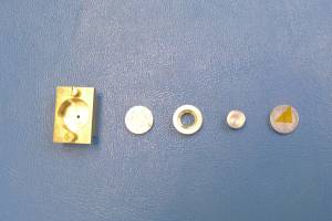 |
| 1230 | Tape pieces together with copper tape around the circumference 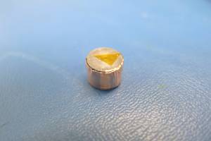 |
| 1240 | Put 9 total pieces of tape around circumference so that it fits snugly in the cup. 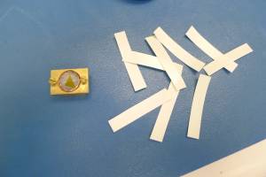 |
| 1250 | Attach cup to motor rod and potentiometer tab 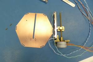 |
| 1250 | Put a 2 mm wide copper tape blocker on the source slit, 5.5-7.5 mm from the source plate center, away from motor 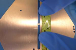 |
| 1300 | Put a 3 mm wide copper tape blocker on the source slit, 24-27 mm from the source plate center, away from motor 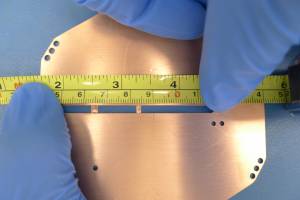 |
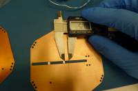
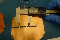
| 1400 | Decide instead to use chunks of indium as the slit blockers. The indium was smushed to be about the same thickness as the Cu plate (0.043” = 1.09 mm). Each is held on with a strip of copper tape on either side. copper tape is about 0.1 mm thick. Combination of indium and copper should reduce 60kev rate to about 3% of the unblocked rate. |
| Description | Length (mm) |
|---|---|
| Center to blocker 1 edge | 5.20 |
| Blocker 1 width | 2.73 |
| Center to blocker 2 edge | 24.80 |
| Blocker 2 width | 3.13 |
 |  |
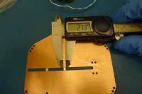 | 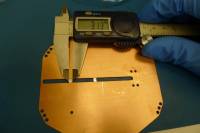 |
| 1445 | Attach motor assembly to plate. Furthest extent of source carriage travel is from (-12.43 mm , + 43.39 mm) relative to the center. |
|---|
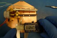 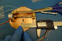 |
| 1500 | Attach thermometer to plate. Attach plate to empty housing. The source housing orientation was constrained to only fit on the detector housing in a couple orientations due to a defect in the G106 housing. We chose the housing and motor orientation such that the source will move outwards towards channel PBS2 or in the direction of DIB 2. |
|---|
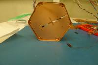 | 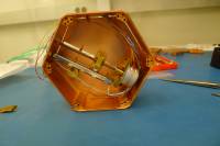 | 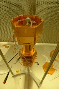 |
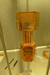
| 1520 | Assemble the detector and source stack. Plug the motor wiring harness into pins 1-7 of tower face 3. Use a bunch of copper tape to cover the wire hole in the source housing and the wires themselves. |
|---|
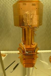 |  |
| 1540 | Install side coaxes. |
|---|---|
| 1600 | Perform tower electrical checks. Everything looks good! |
| 1700 | Install adapter plate on tower. |
| Detector | G106a | DIB | 1 | ||
|---|---|---|---|---|---|
| side coax | ST-3-3 | date/who: | 09/17/2019 | NM & ZW | |
| face | 1 | ||||
| +lead | - lead | signal | typical | previous | measured |
| 1 | 2 | QET A | 100 to 200 Ω | 135Ω | 131Ω |
| 2 | 4 | QETA-B | 100 to 200 Ω | 216Ω | 184Ω |
| 3 | 4 | QET B | 100 to 200 Ω | 201Ω | 183Ω |
| 4 | 6 | QETB-C | 100 to 200 Ω | 220Ω | 226Ω |
| 5 | 6 | QET C | 100 to 200 Ω | 197Ω | 192Ω |
| 6 | 8 | QETC-D | 100 to 200 Ω | 209Ω | 194Ω |
| 7 | 8 | QET D | 100 to 200 Ω | 163Ω | 146Ω |
| 2 | 8 | QETA-D | 100 to 200 Ω | 188Ω | 173Ω |
| chassis | 9 | LED1 Rforward | 8 to 9 MΩ | 771 kΩ | 761kΩ |
| chassis | 9 | LED1 Vforward | 1.0 to 1.1 V | 1.097 V | 1.106V |
| 9 | chassis | LED1 Rreverse | <1 nS | <0.3 nS | <0.1nS |
| chassis | 10 | LED2 Vforward | 8 to 9 MΩ | open | |
| chassis | 10 | LED2 Vforward | 1.0 to 1.1 V | open | open |
| 10 | chassis | LED2 Rreverse | <1 nS | <.2 nS | <0.1nS |
| 1 | 11 | Qo Rbias | 24 to 26 nS | 25 nS | 25.4nS |
| 12 | 11 | Qo C coupling | <1 nS | <0.5 nS | <0.2nS |
| 12 | 13 | Qo Rfeedback | 24 to 26 nS | 25 nS | 25.5nS |
| 1 | 14 | Qi Rbias | 24 to 26 nS | 25 nS | 25.3nS |
| 15 | 14 | Qi C coupling | <1 nS | <0.2 nS | <0.1nS |
| 15 | 16 | Qi Rfeedback | 24 to 26 nS | 25 nS | 25.4nS |
| All pins → Ground | <1.0nS | ||||
| Detector | G106a | DIB | 2 | ||
|---|---|---|---|---|---|
| side coax | ST-3-10 | date/who: | 9/17/2019 | NM & ZW | |
| face | 4 | ||||
| +lead | - lead | signal | typical | previous | measured |
| 1 | 2 | QET A | 100 to 200 Ω | 214 Ω | 135 Ω |
| 2 | 4 | QETA-B | 100 to 200 Ω | 198 Ω | 193 Ω |
| 3 | 4 | QET B | 100 to 200 Ω | 135 Ω | 180 Ω |
| 4 | 6 | QETB-C | 100 to 200 Ω | 196 Ω | 184 Ω |
| 5 | 6 | QET C | 100 to 200 Ω | 181 Ω | 134 Ω |
| 6 | 8 | QETC-D | 100 to 200 Ω | 187 Ω | 184 Ω |
| 7 | 8 | QET D | 100 to 200 Ω | 134 Ω | 134 Ω |
| 2 | 8 | QETA-D | 100 to 200 Ω | 208 Ω | 204 Ω |
| chassis | 9 | LED1 Rforward | 8 to 9 MΩ | 771 kΩ | 760 kΩ |
| chassis | 9 | LED1 Vforward | 1.0 to 1.1 V | 1.097 V | 1.11 V |
| 9 | chassis | LED1 Rreverse | <1 nS | <0.2 nS | <0.1 nS |
| chassis | 10 | LED2 Rforward | 8 to 9 MΩ | 739 kΩ | 729 kΩ |
| chassis | 10 | LED2 Vforward | 1.0 to 1.1 V | 1.096 V | 1.11 V |
| 10 | chassis | LED2 Rreverse | <1 nS | <3 nS | 3 nS |
| 1 | 11 | Qo Rbias | 24 to 26 nS | 26 nS | 26.2 nS |
| 12 | 11 | Qo C coupling | <1 nS | <0.3 nS | <0.2 nS |
| 12 | 13 | Qo Rfeedback | 24 to 26 nS | 26 nS | 26.3 nS |
| 1 | 14 | Qi Rbias | 24 to 26 nS | 25 nS | 25.2 nS |
| 15 | 14 | Qi C coupling | <1 nS | <0.2 nS | <0.2 nS |
| 15 | 16 | Qi Rfeedback | 24 to 26 nS | 26 nS | 26.3 nS |
| All pins → Ground | <1 nS | ||||
| Detector | G106a | DIB | 3 | ||
|---|---|---|---|---|---|
| side coax | ST-3-8 | date/who: | 09/17/2019 | NM & ZW | |
| face | 5 | ||||
| +lead | - lead | signal | typical | previous | measured |
| 1 | 2 | QET A | 100 to 200 Ω | 198Ω | 201 Ω |
| 2 | 4 | QETA-B | 100 to 200 Ω | 243Ω | 241 Ω |
| 3 | 4 | QET B | 100 to 200 Ω | 222Ω | 221 Ω |
| 4 | 6 | QETB-C | 100 to 200 Ω | 181Ω | 186 Ω |
| 5 | 6 | QET C | 100 to 200 Ω | 167Ω | 172 Ω |
| 6 | 8 | QETC-D | 100 to 200 Ω | 177Ω | 185 Ω |
| 7 | 8 | QET D | 100 to 200 Ω | 149Ω | 188 Ω |
| 2 | 8 | QETA-D | 100 to 200 Ω | 207Ω | 211 Ω |
| chassis | 9 | LED1 Rforward | 8 to 9 MΩ | 769 kΩ | 757 kΩ |
| chassis | 9 | LED1 Vforward | 1.0 to 1.1 V | 1.094 V | 1.11 V |
| 9 | chassis | LED1 Rreverse | <1 nS | 60 - inf nS | <1 nS |
| chassis | 10 | LED2 Rforward | 8 to 9 MΩ | ~190 kΩ | 220 kΩ |
| chassis | 10 | LED2 Vforward | 1.0 to 1.1 V | 1.076 V | 1.11 V |
| 10 | chassis | LED2 Rreverse | <1 nS | inf nS (closed connection) | 7.5 MΩ |
| 1 | 11 | Qo Rbias | 24 to 26 nS | 25 nS | <0.1 nS |
| 12 | 11 | Qo C coupling | <1 nS | <0.5 nS | <0.2 nS |
| 12 | 13 | Qo Rfeedback | 24 to 26 nS | 25 nS | 25.2 nS |
| 1 | 14 | Qi Rbias | 24 to 26 nS | 25 nS | <0.1 nS |
| 15 | 14 | Qi C coupling | <1 nS | <0.2 nS | <0.1 nS |
| 15 | 16 | Qi Rfeedback | 24 to 26 nS | 25 nS | 25.2 nS |
| All pins → Ground | <1.0nS | (Except for LED pins) | |||
| Detector | G106a | DIB | Motor | ||
|---|---|---|---|---|---|
| side coax | - | date/who: | 09/17/2019 | NM | |
| face | 3 | ||||
| +lead | - lead | signal | typical | previous | measured |
| 1 | 2 | Motor Coil A | 5-10 kΩ | - | 7.13 kΩ |
| 3 | 4 | Motor Coil B | 5-10 kΩ | - | 7.54 kΩ |
| 5 | 6 | Slide Pot 2-1 | 1-10 kΩ | - | 2.679 kΩ |
| 5 | 7 | Slide Pot 2-3 | 1-10 kΩ | 181Ω | 7.37 kΩ |
| 6 | 7 | Slide Pot 1-3 | 10 kΩ | 167Ω | 9.88 kΩ |