2019/06/11 (Tuesday)
| Setup | DIB1/3/4 → 3.2 MHz filters 2/3/1 → cable 3/1/2 → gender changer ?/3/2 → HVConn 1/3/2 → HV 1/2 → DCRCX(4)/DCRC55(1) DCRC33(2) → 1kV power supply → HV input Two walls of the lead/poly shield are up. |
|---|---|
| 0910 | Tower/MC/Coldplate = 42.7/30.8/177 mK, Still = 1.01 K / 0.090 mbar, G1/G2 = 158/144 mbar, 1K Pot = 1.63 K / 24 mbar. MB = 73.4% |
| 0915 | Fill LN2 Cold trap bath |
| 0929 | Start a 75 min series at HV = 200→400V, rate +2.64V/min with 10% prebias for 2 minutes, flash at end with 30 min wait. CDMS detector: Driver Gains = 1x, DCRC4/1 QET biases = (490/400/490)/(420/480/450) uA, Front-End Gains = (2/2/3)/(5/5/5) 1000 BOR and 1000 EOR randoms, trigger on DCRC1pB/C/D threshold = 6/6/6. Use sequence HVdrift_200V_2p64VPM_prebias_10_2_dur_75min_flashDCRC_1_4.msl |
- The noise width in this data appears to be around 23 eVee (without channel balancing)
- The noise width of the weekend data - same HV but different QET biases - is 27.2 eVee (also without channel balancing)
- so it does indeed look like the higher QET biases (which are set above the oscillation regimes in the inner-ring channels) are better.
| 1205 | Start a 75 min series at HV = 200→400V, rate +2.64V/min with 10% prebias for 2 minutes, flash at end with 30 min wait. CDMS detector: Driver Gains = 1x, DCRC4/1 QET biases = (490/400/490)/(420/480/450) uA, Front-End Gains = (2/2/3)/(5/5/5) 1000 BOR and 1000 EOR randoms, trigger on DCRC1pB/C/D threshold = 6/6/6. Use sequence HVdrift_200V_2p64VPM_prebias_10_2_dur_75min_flashDCRC_1_4.msl |
|---|---|
| 1430 | Put more of the lead shield up |
| Before the shield the drift rate was 3.9 V/min, with two walls it was 2.64 V/min, so now it is maybe around 2.0 V/min. Let's try 0.034 V/sec which is 2.04 V/min. |
[fritts@jiajin /home/hep/cdmssoft/scdmsDAQ/MidasDAQ/online/scripts/pysequencer]: python HVscan.py -iDCRC 2 -HVs 200 -HVcalFile HV_calibrations/HV_DCRC2_control_cals_440V_190603.txt -HVdriftRate 0.034 -HVpreBias 10/2 -tSeries 98 -DCRCs2Flash 1,4 > ../../sequencer/HVdrift_200V_2p04VPM_prebias_10_2_dur_98min_flashDCRC_1_4.msl
| 1455 | Put up lead shielding (5 layers) on the bottom of the detector and 5 layers on the North wall. Poly layers (a total of 5) installed on the detector bottom. |
|---|---|
| 1503 | Start a 98 min series at HV = 200→400V, rate +2.04V/min with 10% prebias for 2 minutes, flash at end with 30 min wait. CDMS detector: Driver Gains = 1x, DCRC4/1 QET biases = (490/400/490)/(420/480/450) uA, Front-End Gains = (2/2/3)/(5/5/5) 1000 BOR and 1000 EOR randoms, trigger on DCRC1pB/C/D threshold = 6/6/6. Use sequence HVdrift_200V_2p04VPM_prebias_10_2_dur_98min_flashDCRC_1_4.msl |
| 1504 | The fridge windows computer, spa-vuk1, locked up - I did a hard reboot. |
| 1515 | DCRC1pC is railed. Looks like it has been since the beginning, so noise processing will be no good. |
| 1517 | Abort data series by hitting Stop on the main MIDAS page. But we'll leave the sequence going. Should be able to restart after unrailing and catch the rest of the bias-drift period. |
| 1521 | Restart data after unrailing DCRC1pC. Same configuration as 1503 above. |
| 1545 | Looking at the first few minutes of processed data, it looks like the drift rate might be too low by about 0.3 V/min. |
| 1555 | Fill LN2 Cold trap bath |
| 1605 | Notice that towerfe3_01 is not running and SQUIDTuningGUI crashes if we try to look at pulses. Abort data series and stop sequencer. |
| 1610 | Manually turn down HV. |
| 1613 | Restart DCRC programs and flash for 30s. |
| Looking at more of the processed data, estimate that drift rate should be increased by 0.32 V/min. Let's try 2.34 V/min = 0.039 V/s |
[fritts@jiajin /home/hep/cdmssoft/scdmsDAQ/MidasDAQ/online/scripts/pysequencer]: python HVscan.py -iDCRC 2 -HVs 200 -HVcalFile HV_calibrations/HV_DCRC2_control_cals_440V_190603.txt -HVdriftRate 0.039 -HVpreBias 10/2 -tSeries 86 -DCRCs2Flash 1,4 > ../../sequencer/HVdrift_200V_2p34VPM_prebias_10_2_dur_86min_flashDCRC_1_4.msl
| 1650 | Channels all look good still. |
|---|---|
| 1652 | Start an 86 min series at HV = 200→400V, rate +2.34V/min with 10% prebias for 2 minutes, flash at end with 30 min wait. CDMS detector: Driver Gains = 1x, DCRC4/1 QET biases = (490/400/490)/(420/480/450) uA, Front-End Gains = (2/2/3)/(5/5/5) 1000 BOR and 1000 EOR randoms, trigger on DCRC1pB/C/D threshold = 6/6/6. Use sequence HVdrift_200V_2p34VPM_prebias_10_2_dur_86min_flashDCRC_1_4.msl |
| 2129 | Start an 86 min series at HV = 200→400V, rate +2.34V/min with 10% prebias for 2 minutes, flash at end with 30 min wait. CDMS detector: Driver Gains = 1x, DCRC4/1 QET biases = (490/400/490)/(420/480/450) uA, Front-End Gains = (2/2/3)/(5/5/5) 1000 BOR and 1000 EOR randoms, trigger on DCRC1pB/C/D threshold = 6/6/6. Use sequence HVdrift_200V_2p34VPM_prebias_10_2_dur_86min_flashDCRC_1_4.msl |
- Data above has noise width around 24.2 eVee (unbalanced)
- Am lines are better resolved than in the SiHV run:
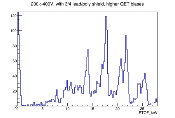 |  |
- Looks like there's an additional line at 8 keV
- note that this plot has a high-pF selection, and the new 8 keV line is showing up in high-pF, so it seems like a line associated with the Am source
- It turns out that an unbalanced PsumOF gives a better noise width than PTOF does: 19.8 eVee instead of 24.2 eVee. Why? (It looks like the peaks appear higher in Psum than in PT.)