2017/09/11 (Monday)
| Status | Both LN2 traps warm and pumped out. Mixture in dump (LHe cold trap isolated at around 20 K). 1K Pot needle valve open. Cryostat vacuum jacket pumped out. |
|---|
| DIB | Side Coax | Tower Face | Direction | Stripline |
|---|---|---|---|---|
| DIB 1 | ZB1-1-9 | 5 | E | 19 |
| DIB 3 | ZB1-1-11 | 3 | SW | 20 |
| DIB 4 | ZB1-6 | 2 | W | 27 |
| 1030 | Consulting k100coldhardware, the tower we are using has two bad faces, 1 and 6. By the table above we'll use tower faces 2,3,5. Verified that all the traces are good in these tower faces using the multimeter. |
|---|---|
| 1040 | Attach detector stack to tower connector spool |
| 1050 | Assemble the new side coax extenders. Attach white poly pin guides to copper spacers. The spacers are marked T for Tower side, SC on Side Coax side. The pins on the tower are not centered (they are shifted to the left as you face the detector-end-up tower), so the pin guides must be attached in the correct orientation. |
 | 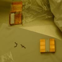 | 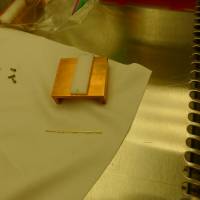 | 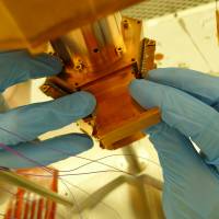 |
| 620 | 621 | 622 | 623 |
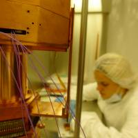
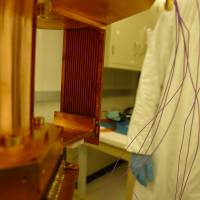
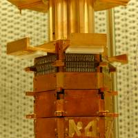
| 1105 | Discovered that the cover plates on the side coaxes are too long. The side coax won't plug into the DIB pins all the way with the plates on because they hit the electrode housing beneath the detector. (It seems they were designed for a detector in Position 1, the closest housing to the tower.) So we are removing the cover plates. This leaves one wall missing for the side coax wires, exposing them on the inner side. |
|---|
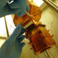 |  |  |  |
| 624 | 625 | 626 | 627 |
| 1120 | We'll only use pins on the extenders where needed. Only the connected charge channels, 3 pins each at the tower side, plus the pins listed below to bias the LEDs and the electrode, plus pins for the DIB LEDs in case we want to use them. |
|---|---|
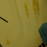
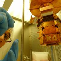
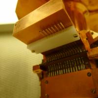
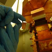
| 1125 | Assembling pins for extender plugs. Each is 4 mill-max pins, 3 of standard length and 1 cut somewhat shorter. |
 |  |  |  |
| 628 | 629 | 630 | 631 |
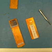
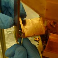
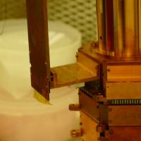
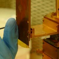
| 1140 | DIB4 side coax is now attached. The extender sockets have to be guided onto the side coax pins one at a time with tweezers. |
|---|
 |  |  |  |
| 632 | 633 | 634 | 635 |
| Elec LED IR1 | DIB3 A @ extender plug |
| Elec LED UV1 | DIB3 B @ extender plug |
| Elec LED IR2 | DIB3 C @ extender plug |
| Elec LED UV2 | DIB3 D @ extender plug |
| Elec bias | DIB1 A+Aret @ extender plug |
| Elec LED Gd1 | attach to tower face with screw |
| Elec LED Gd2 | attach to tower face with screw |
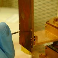
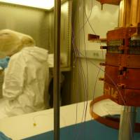
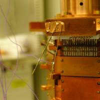
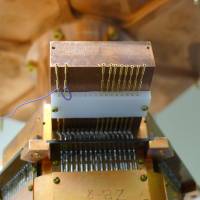
| 1150 | Begin to work on wire connections. The wires from the electrode housing will be soldered to the extender pins, then the connector pins will be inserted through the extender into the tower. |
|---|
 |  |  |  |
| 636 | 637 | 638 | 639 |
| 1500 | Continue soldering LED and electrode wires. |
|---|---|
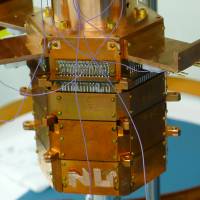
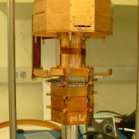
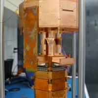
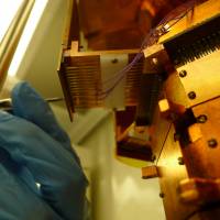
| 1535 | Start attaching remaining two side coaxes |
 |  |  |  |
| 640 | 641 | 642 | 643 |
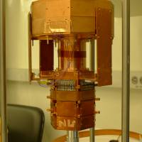
| 1600 | Begin electrical checkout |
|---|
| Tower Level Checkout | |||||
|---|---|---|---|---|---|
| Detector | S1502 | Date | 2017-09-11 | Who | NM MF |
| DIB | 1 | Face | 5 | Side Coax | ZB1-1-9 |
| +lead | - lead | signal | typical | prev. | measured |
| 11 | 14 | Det cont, Rbias | 12 to 13 nS | - | 13 nS |
| 12 | 11 | Qo C coupling | <1 nS | - | 0.4 nS |
| 12 | 13 | Qo Rfeedback | 24 to 26 nS | - | 26 nS |
| 15 | 14 | Qi C coupling | <1 nS | - | 0.4 nS |
| 15 | 16 | Qi Rfeedback | 24 to 26 nS | - | 26 nS |
| 1 | 11 | Electrode isol | <1 nS | - | 0.11 nS |
| All pins | chassis | isolation | <1.0nS | - | <1 nS |
| DIB | 3 | Face | 3 | Side Coax | ZB1-1-11 |
| +lead | - lead | signal | typical | prev. | measured |
| 11 DIB4 | 11 | Det cont, Rbias | 12 to 13 nS | - | 13 nS |
| 12 | 11 | Qo C coupling | <1 nS | - | 0.1 nS |
| 12 | 13 | Qo Rfeedback | 24 to 26 nS | - | 26 nS |
| 15 | 14 | Qi C coupling | <1 nS | - | 0.1 nS |
| 15 | 16 | Qi Rfeedback | 24 to 26 nS | - | 25 nS |
| 2 | chassis | LEDa Rforward | 8 to 9 MΩ | - | 0.8 MΩ |
| 2 | chassis | LEDa Vforward | 1.0 to 1.1 V | - | 1.090 V |
| chassis | 2 | LEDa Rreverse | <1 nS | - | 0.1 nS |
| chassis | 4 | LEDb Rforward | 8 to 9 MΩ | - | 52 kΩ |
| chassis | 4 | LEDb Vforward | 1.0 to 1.1 V | - | 0.782 V |
| 4 | chassis | LEDb Rreverse | <1 nS | - | 59 kΩ |
| 6 | chassis | LEDc Rforward | 8 to 9 MΩ | - | 0.79 MΩ |
| 6 | chassis | LEDc Vforward | 1.0 to 1.1 V | - | 1.090 V |
| chassis | 6 | LEDc Rreverse | <1 nS | - | 0.1 nS |
| chassis | 8 | LEDd Rforward | 8 to 9 MΩ | - | 38 kΩ |
| chassis | 8 | LEDd Vforward | 1.0 to 1.1 V | - | 0.78 V |
| chassis | 8 | LEDd Rreverse | <1 nS | - | 37 kΩ |
| All pins | chassis | isolation | <1.0nS | - | <1 nS |
| DIB | 4 | Face | 2 | Side Coax | ZB1-6 |
| +lead | - lead | signal | typical | prev. | measured |
| 11 | 14 | Det cont, Rbias | 12 to 13 nS | - | 13 nS |
| 12 | 11 | Qo C coupling | <1 nS | - | 0.2 nS |
| 12 | 13 | Qo Rfeedback | 24 to 26 nS | - | 26 nS |
| 15 | 14 | Qi C coupling | <1 nS | - | 0.3 nS |
| 15 | 16 | Qi Rfeedback | 24 to 26 nS | - | 26 nS |
| All pins | chassis | isolation | <1.0nS | - | <1 nS |
 |
| 644 |