Previous Day
| Status | Both LN2 traps warm and pumped out. Mixture in dump (LHe cold trap isolated at around 20 K). 1K Pot needle valve open. Cryostat vacuum jacket pumped out. |
| 0955 | Perform wirebond repair on S1502 qD (DIB3 qO). Used power 480/480, time 40/30, length/drop 50/26. Didn't stick to the detector pad at first, had to open/feed more wire out, then it stuck after “bond off excess”. Resistance checks look good. |
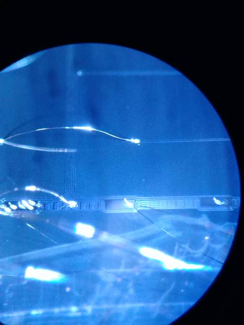
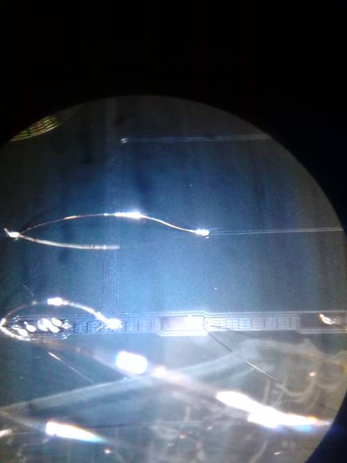
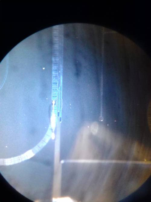
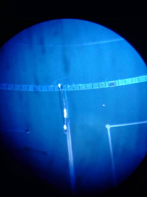
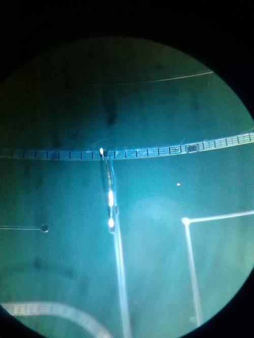
| 1000 | Examined G132 Side1 pF. This is the channel that seemed to have no connection issues but behaved as if open/high R when cold. Looked at it under a microscope and took some pictures. No obvious problems with the traces or wirebond leading from the wirebond pads to the center phonon channel. |
| 1332 | Measuring detector-electrode gap. Used micrometer and flat bar to measure distance from delector/electrode face to housing rims. Measurements indicated the outer rim is where adjascent housings meet. |
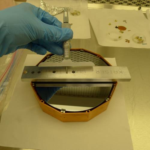
| Housing | Measurement | Length (inches ±0.001) |
| electrode | bar to electrode | 0.3835 |
| electrode | bar to inner rim | 0.4182 |
| electrode | bar to outer rim | 0.4560 |
| crystal | bar to crystal | 0.4940 |
| crystal | bar to inner rim | 0.4290 |
| crystal | bar to outer rim | 0.3842 |
| | Using the outer rim as reference, the electrode is 0.4560“-0.3835”=0.0725“ above and the crystal face is 0.4940”-0.3842“=0.1098” above the outer rim (when stack is upright). This gives us a gap of 0.037“±0.004” between detector and electrode. This is just under 1mm. |
| 1400 | Bill V was able to drill a 6 mil hole in the center of one of our extra 3/8“ lead disks. So we are switching out the 8 mil collimator on qB's source with a 6 mil collimator. |
| 1435 | Assemble stack. Crown, then electrode housing (electrode facing up), then detector housing (bare face downward), then lid, then thermometer over one of the screw holes, then the 6 threaded rods made for this run. |
| 1500 | Proceeded with electrical check at the DIBs but some cross-channel resistances were unusually low. So we took the lid off an measured from pin to channel (second lead directly on detector) |
| Detector Electrical Checkout (open housing) | Date: | 2017 Sep 8 |
| Detector: S1502 | Who: | MF NM |
| Pin | qA | qB | qC | qD | qE |
| DIB1 qI (qA) | 2 | 16 | 200 | 200 | 14 |
| DIB4 qI (qB) | 14 | 2 | 200 | 200 | 30 |
| DIB1 qO (qC) | 200 | 200 | 3 | 200 | 200 |
| DIB3 qO (qD) | 200 | 200 | 200 | 4 | 200 |
| DIB4 qO (qE) | 11 | 20 | 200 | 200 | 5 |
| all measurements in Ω. (for >100 approximate values shown) |
Examining table above suggests 1 short between qA and qB and another between qA and qE. Looking closely at detector, one bond seemed to be touching the detector surface - gently pushed it up with scalpel. For the other short it looked like a tiny piece of grit was between the T-shaped bond pad and the adjacent channel - removed this with rolled up piece of wipe dampened with methanol.
| Detector Electrical Checkout (open housing) | Date: | 2017 Sep 8 |
| Detector: S1502 | Who: | MF NM | | |
| Pin | qA | qB | qC | qD | qE |
| DIB1 qI (qA) | 2 | 200 | 200 | 300 | 150 |
| DIB4 qI (qB) | 200 | 2 | 200 | 300 | 300 |
| DIB1 qO (qC) | 300 | 200 | 3 | 300 | 300 |
| DIB3 qO (qD) | 300 | 300 | 300 | 4 | 300 |
| DIB4 qO (qE) | 100 | 300 | 300 | 300 | 5 |
| all measurements in Ω. (for >100 approximate values shown) |
This seems to have fixed the shorts!
| 1525 | Reassemble stack. Unfortunately the threads in the crown seem to be getting worse… |
| Detector Electrical Checkout | Date: | 2017 Sep 8 |
| Detector: S1502 | Who: | MF NM |
| +lead | -lead | Measurement | Value |
| DIB1 qO | DIB1 qI | qC to qA | 300 Ω |
| DIB1 qI | DIB3 qO | qA to qD | 500 Ω |
| DIB4 qO | DIB4 qI | qE to qB | 700 Ω |
| DIB4 qO | DIB1 qO | qE to qC | 640 Ω |
| DIB3 qO | DIB4 qI | qD to qB | 480 Ω |
| DIB1 qO | chassis | | <20 nS |
| DIB1 qI | chassis | | 10 nS |
| DIB3 qO | chassis | | 8.5 MΩ |
| DIB4 qO | chassis | | 8.5 MΩ |
| DIB4 qI | chassis | | 8.5 MΩ |
| note: qI is the last pin on the DIB |
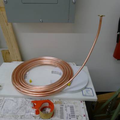
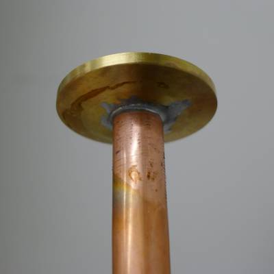
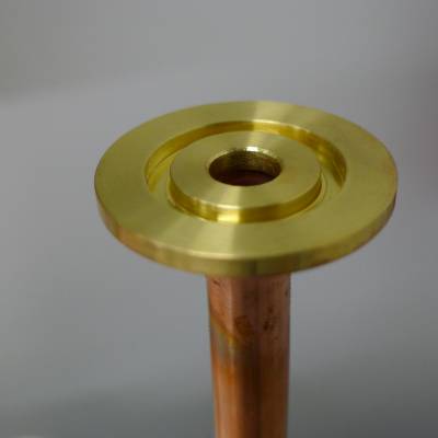
| 1630 | Start building recovery gas warming tube - 50' of 1/2” OD copper “refrigeration tubing” and two brass 25mm KF blanks. Drilled 3/8“ hole and 1/2” flat depression into blank then solder onto tube. |
Next Day