2017/09/07 (Thursday)
| Status | Both LN2 traps warm and pumped out. Mixture in dump (LHe cold trap isolated at around 20 K). 1K Pot needle valve open. Cryostat vacuum jacket pumped out. |
|---|---|
| 1025 | Make a new collimator - Help from Bill Voje to drill a 8 mil hole in one of the small (3/8“) back plates. Will try to drill another plate with a 6 mil hole tomorrow (assuming the drill head arrives). |
| 1105 | Start assembling Am sources in holders and attaching to electrode. What is the correct orientation for the encapsulated sources?? With the small source you can see through the plastic, and at first I thought it was clear that the source was on the side with the white sticker label, not the side with the radiation symbol. So I thought the white side should face the detector. But on 2015 Nov 20 there's a picture implying that the radiation-symbol side faces the detector, and looking closer it looks like the actual Am is in the middle. So we are mounting them with the radiation symbol facing the detector. As for the large source, there's a white label on one side and opaque red on the other. The white side has a bit of a bump, so it seems like the Am may be closer to that side. So we are mounting it with the white label side facing the detector. (It may not matter much, the 60keV gammas may make it through the plastic easily enough regardless.) |
| 1125 | Finish mounting the four Am sources : |
| AM-241 Source positions | |
|---|---|
| Q channel | source |
| B (second outermost ring) | Small encapsulated source with |
| C (third outermost ring) | Large encapsulated source with 6 mil collimator |
| D (ring nearest center) | Small encapsulated source with 6 mil collimator |
| E (center) | Bare source with 18 mil collimator |
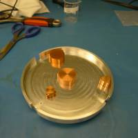 |
| Electrode with sources |
| 1145 | Desolder LED chips and electrode connector from their previous DIB wires. We won't be using the DIB on the electrode housing this time. |
|---|
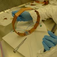 |
| Electrode housing with DIB still in place from Run 60 |
| 1200 | Begin mounting electrode. Used two 20 mil spacers both on the same side, so that electrode is as far from detector as possible. According to calculations this should give about the right spacing. |
|---|
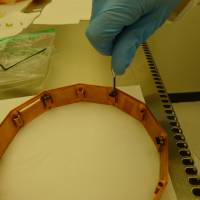 |
| Electrode housing |
| 1212 | Calculations neglected to include flipping the detector in its housing! We discovered this by trying a test stack-up with a strip of fabric kimwipe between detector and electrode. We found that the detector and electrode would be touching if mounted. There is a set of two 20 mil spacers on the detector housing which, when the detector was flipped, made the detector sit 40 mil closer to the electrode. |
|---|---|
| 1215 | Moving detector spacers to opposite side of detector housing. In order to avoid breaking wirebonds, we're doing this one half at a time. i.e. remove 3 sets of spacers on one side, flip housing, insert spacers on opposite side, then repeat. |
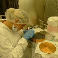 | 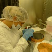 |
| Changing clamp spacing on detector. | |
| 1225 | Mount LED chips onto electrode. |
|---|
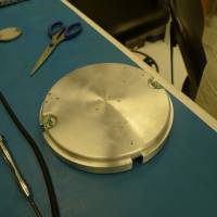 |
| Electrode with LEDs |
| 1245 | Soldered long wires to LEDs (1 UV, 1 IR on each of 2 chips, plus one ground wire each) and to the electrode connector, all attached to electrode. |
|---|
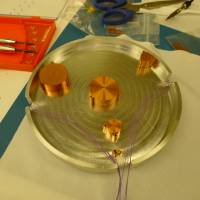 | 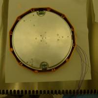 |
| Electrode with wiring | Electrode in housing |
| 1330 | Finish redoing the clamps for the detector. Then do an electrical check: one channel is broken, the others are intact. Broken bond is the detector side of the DIB-to-detector bond for pD (DIB3 qO). |
|---|
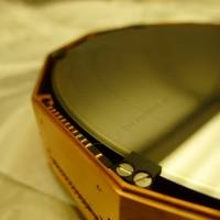 | 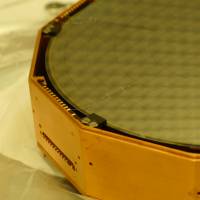 |
| One broken wirebond on detector. | |
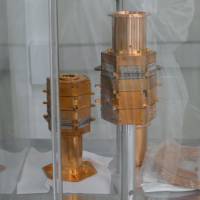 |
| Tower with short spool and standard tower with longer spool |