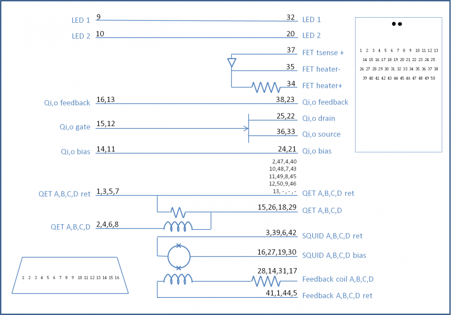
For the next run, we will need to check to see whether we have good charge channels. We should check the SQUETs and the side coaxes and the tower faces. Here's an example of a side coax checkout from
23 May 2016:
| Side coax | ZB-4-4 |
| | date: | 2015-05-23 | who: | MF NM |
| +lead | - lead | signal | typical | measured |
| D11 | T11 | Qo Rbias | 25 nS | 26 nS |
| T12 | T13 | Qo Rfeedback | 25 nS | 26 nS |
| D11 | T12 | Qo C coupling | <1 nS | 0.2 nS |
| D12 | T14 | Qi Rbias | 25 nS | 27 nS |
| T15 | T16 | Qi Rfeedback | 25 nS | 26 nS |
| D12 | T15 | Qi C coupling | <1 nS | 36 nS |
The above is an example of a blown Qinner coupling capacitor.
| 1420 | Remove G132 from purge cabinet. |
| | G132 electrical checkout: |
| Detector | G132 | DIB | 1 | |
| | | date/who: | 2017-06-19 | NM GR |
| +lead | - lead | signal | typical | at SLAC | measured |
| 1 | 2 | QET A | 100 to 200 Ω | 73.0 Ω | 72 Ω |
| 3 | 4 | QET B | 100 to 200 Ω | 82.8 Ω | 81.1 Ω |
| 5 | 6 | QET C | 100 to 200 Ω | 58.7 Ω | 58.8 Ω |
| 7 | 8 | QET D | 100 to 200 Ω | 11.3 Ω | 11.2 Ω |
| 9 | chassis | LED1 Rforward | 8 to 9 MΩ | present | 711 kΩ |
| 9 | chassis | LED1 Vforward | 1.0 to 1.1 V | present | 1.037 V |
| chassis | 9 | LED1 Rreverse | <1 nS | present | 1.4 nS |
| 10 | chassis | LED2 Rforward | 8 to 9 MΩ | present | 730 kΩ |
| 10 | chassis | LED2 Vforward | 1.0 to 1.1 V | present | 1.041 V |
| chassis | 10 | LED2 Rreverse | <1 nS | present | 1.3 nS |
| 11 | 12 | Qo-Qi | | 55.0 Ω | 56 Ω |
| 12 | 11 | Qi-Qo | | 56.1 Ω | 52.1 Ω |
| 1-8 | chassis | | <1 nS | ~100 Ω | <1 nS |
| Detector | G132 | DIB | 3 | |
| | | date/who: | 2017-06-19 | NM GR |
| +lead | - lead | signal | typical | at SLAC | measured |
| 1 | 2 | QET A | 100 to 200 Ω | 8.5 Ω | 8.5 Ω |
| 3 | 4 | QET B | 100 to 200 Ω | 23.9 Ω | 24.0 Ω |
| 5 | 6 | QET C | 100 to 200 Ω | 10.8 Ω | 19.8 Ω, initially unstable ~5 MΩ |
| 7 | 8 | QET D | 100 to 200 Ω | 29.4 Ω | 27.9 Ω |
| 9 | chassis | LED1 Rforward | 8 to 9 MΩ | n/c | n/c |
| 9 | chassis | LED1 Vforward | 1.0 to 1.1 V | n/c | n/c |
| chassis | 9 | LED1 Rreverse | <1 nS | n/c | n/c |
| 10 | chassis | LED2 Rforward | 8 to 9 MΩ | n/c | n/c |
| 10 | chassis | LED2 Vforward | 1.0 to 1.1 V | n/c | n/c |
| chassis | 10 | LED2 Rreverse | <1 nS | n/c | n/c |
| 11 | 12 | Qo-Qi | | 42.8 Ω | 42.4 Ω |
| 12 | 11 | Qi-Qo | | 35.1 Ω | 41.1 Ω |
| 1-8 | chassis | | <1 nS | ~100 Ω | <1 nS |
Initially QET C looked open, 1 to 5 was 10 Ω, 1 to 6 was open, but then after some measurements it stablized. Maybe a lose DIB pin or shoddy DIB?
| Detector | G132 | DIB | 4 | |
| | | date/who: | 2017-06-19 | NM GR |
| +lead | - lead | signal | typical | at SLAC | measured |
| 1 | 2 | QET A | 100 to 200 Ω | 38.4 Ω | 38.4 Ω |
| 3 | 4 | QET B | 100 to 200 Ω | 81.5 Ω | 80.2 Ω |
| 5 | 6 | QET C | 100 to 200 Ω | 76.3 Ω | 75.4 Ω |
| 7 | 8 | QET D | 100 to 200 Ω | 27.8 Ω | 27.8 Ω |
| 9 | chassis | LED1 Rforward | 8 to 9 MΩ | n/c | n/c |
| 9 | chassis | LED1 Vforward | 1.0 to 1.1 V | n/c | n/c |
| chassis | 9 | LED1 Rreverse | <1 nS | n/c | n/c |
| 10 | chassis | LED2 Rforward | 8 to 9 MΩ | n/c | n/c |
| 10 | chassis | LED2 Vforward | 1.0 to 1.1 V | n/c | n/c |
| chassis | 10 | LED2 Rreverse | <1 nS | n/c | n/c |
| 11 | 12 | Qo-Qi | | n/c | n/c |
| 12 | 11 | Qi-Qo | | n/c | n/c |
| 1-8 | chassis | | <1 nS | ~100 Ω | <1 nS |
Although SLAC measured 100 Ω between phonons and chassis, we found them all to be open.
| 1508 | Returned G132 to purge cabinet. |
| 1509 | Removed Tower and S101 from purge cabinet. |
| Side coax | ST-3-3 |
| | date: | 2015-06-19 | who: | NM GR |
| +lead | - lead | signal | typical | measured |
| D11 | T11 | Qo Rbias | 25 nS | 25.53 nS |
| T12 | T13 | Qo Rfeedback | 25 nS | n/c |
| D11 | T12 | Qo C coupling | <1 nS | 0.3 nS |
| D12 | T14 | Qi Rbias | 25 nS | 25.62 nS |
| T15 | T16 | Qi Rfeedback | 25 nS | n/c |
| D12 | T15 | Qi C coupling | <1 nS | 0.17 nS |
With magnifying glass you can clearly see the wire bonds broken on both sets of feedback resistors.
| Side coax | ST-3-10 |
| | date: | 2015-06-19 | who: | NM MF |
| +lead | - lead | signal | typical | measured |
| D11 | T11 | Qo Rbias | 25 nS | <1 nS |
| T12 | T13 | Qo Rfeedback | 25 nS | 26.6 nS |
| D11 | T12 | Qo C coupling | <1 nS | 1.2 nS |
| D12 | T14 | Qi Rbias | 25 nS | <1 nS |
| T15 | T16 | Qi Rfeedback | 25 nS | 26.5 nS |
| D12 | T15 | Qi C coupling | <1 nS | 2.0 nS |
With magnifying glass you can clearly see wire bonds broken on both sets of bias resistors.
| Side coax | ST-3-9 |
| | date: | 2015-06-19 | who: | NM MF |
| +lead | - lead | signal | typical | measured |
| D11 | T11 | Qo Rbias | 25 nS | 27.95 nS |
| T12 | T13 | Qo Rfeedback | 25 nS | <1 nS |
| D11 | T12 | Qo C coupling | <1 nS | 0.8 nS |
| D12 | T14 | Qi Rbias | 25 nS | 25.86 nS |
| T15 | T16 | Qi Rfeedback | 25 nS | 25.7 nS |
| D12 | T15 | Qi C coupling | <1 nS | 0.4 nS |
All three of these need wirebonds repaired on their resistor arrays.
| ST-3-9 | ST-3-10 | ST-3-3 |
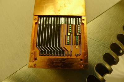 | 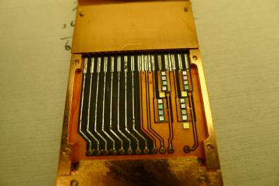 | 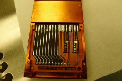 |
| Broken bonds visible on upper left (qO feedback) | Broken bonds on lower resistor arrays (qI and qO bias) | Broken bonds on upper resistor arrays (qI and qO feedback) |
| 1610 | Begin disassembling stack. We will try leaving the four external LED wires soldered to the side coax extender pins, since we'll be using these again. |
| 1623 | Place S101 in purge cabinet. |
| 1627 | Return tower base to purge cabinet. Return source/LED holder to purge cabinet with thermometer, external LED wires and extender plugs still connected. |
Next Day