2017/03/01 (Wednesday)
| Setup: DIB1/3/4 → 3.2 MHz filters 3/1/2 → cable 3/1/2 →gender changer 3/1/2 → HVConn 1/3/2 → HV 1/2 → DCRC55/DCRC33 | |
| Took Ba data overnight. Data looks good throughout the overnight sequence. | |
| 0920 | Remove 133Ba source from fridge and return to safe |
| 0925 | Tower = 33.5 mK, Main bath = 36.3% |
| 0930 | Fill LN2 cold trap bath |
| 1020 | Finish IbIs on DCRC1pB / DIB1pB |
| 1040 | Did a test on DCRC1pB involving the Driver Gain. The theory is that you can maybe use driver gain to help determine the voltage offset. At a certain output, changing the driver gain should amplify the output from the offset point. The test involved measuring IbIs with QET biases of 0, 5, and 10 μA and repeating for different Driver Gains, with the same driver offset in each case. Presumably at QET Bias = 0 the output would be the same at all gain settings, because the true output voltage should be zero. |
| Driver Offset = 0.45 |
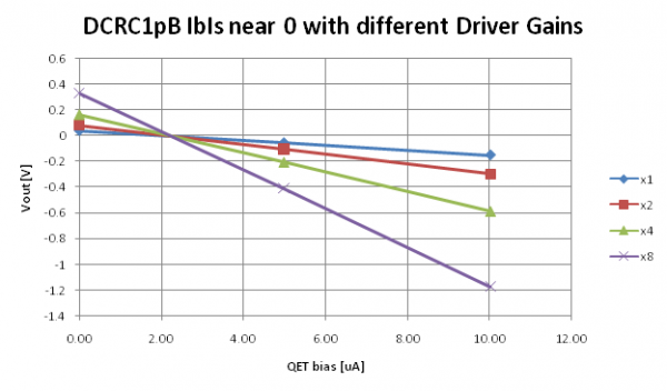 |
| Note that the lines intersect but not at 0 μA. This suggests that there is an offset in QET bias a little over 2 μA. Offset appears to be at 2.24 ± 0.01 μA. |
| Driver Offset = 0.15 |
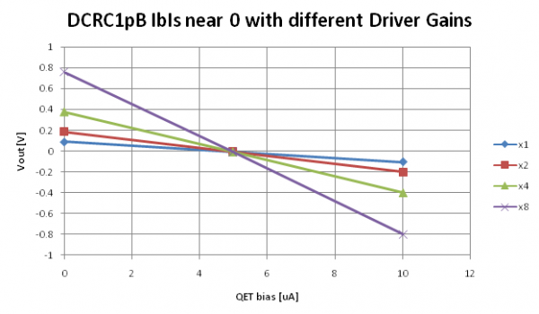 |
| Further tests of Driver Offsets and Driver Gains were a bit confusing, so we re-did the above measurement using a different driver offset. As can be seen the apparent QET bias offset is not at the same place. So something more complicated is happening. |
Actually it seems to be something simple. The Driver Gain seems to apply a multiplier to the numerical output value. Notice that in the above plots that the intersection point is at Vout=0 - this is not a coincidence. So the effect of the Driver Gain setting depends on where the driver offset has been set. And there is no way to tease out the voltage offset by playing with the Driver Gain. So forget I mentioned it.
| 1045 | Start LHe transfer (MB = 32.2%). Pressure was about 3.25 psi, lowered to about 1.5 psi to see how this affects Helium recovery rate. (raised to 2.5 psi) |
|---|---|
| 1045 | Tower/MC/Coldplate = 33.5/31.0/193 mK, Still = 1.26 K / 0.110 mbar, G1/G2 = 240/225 mbar, 1K Pot = 1.683 K / 30 mbar, Main bath = 32.2%. Boil off rate: close to slow mode. |
| 1227 | End LHe transfer (MB = 91.1%). |
| 1309 | Release pressure from MB. Will stop doing this for the next week or so to observe if this affects boil off rate. |
| 1518 | Begin 1 hour bake in preparation for HV data taking. Tower reaches 485 mK. Condenser pressure increases by 40 mbar. |
| 1620 | Tower has cooled to 150 mK |
| 1630 | Tower has cooled to 53 mK |
| 1658 | Tower has cooled to 35 mK |
| 1659 | Prebias to HV = 15V |
| 1710 | Fill LN2 cold trap full. |
| 1717 | Reduce HV to 10 V , Vleak=-5.4 mV, V_crystal = 12.4 V |
| 1718 | Start 10, 1-hour data series of 10V HV data with Frontend Gain = (20/20/5)/(6/4/3), OG = 8/4, with 1000 beginning and ending randoms, 30s flashing with 10 minute cooldown, and a 35ADC bin threshold trigger on DCRC1 pA Only later realized there was no point in flashing since the HV was always on. Additionally, DIB2PC was railed the entire time. |
| 1717 | HV = 10 V , Vleak = 0.1 mV, V_crystal = 9.96 V |
| 1717 | HV = 10 V , Vleak = 0±0.1 mV, V_crystal = 10±0.04 V |