2017/02/28 (Tuesday)
| Setup: DIB1/3/4 → 3.2 MHz filters 3/1/2 → cable 3/1/2 →gender changer 3/1/2 → HVConn 1/3/2 → HV 1/2 → DCRC55/DCRC33 | |
| Took data overnight. | |
| 0900 | Tower = 33.5 mK. Main bath = 72.7%. |
| 0905 | Fill LN2 cold trap bath |
| 0935 | Finish IbIs on DCRC1pB / DIB1pB |
| 1045 | Set up to do another HV sweep and measure phonon baseline shift of DCRC1pB, biased at 140 μA. FE gain = 20, driver gain = x8, driver offset = -0.022 Increasing HV in steps of 10 V, then waiting for Vtest to settle to values similar to the late values on Wednesday's test |
| HV [V] | Vtest [mV] | Ileak [nA] | Vcrystal [V] | DCRC1pB baseline [V] |
|---|---|---|---|---|
| 0.016 | -0.4 | -0.44 | 0.192 | -0.8083 |
| 10.05 | 1.1 | 1.21 | 9.566 | -0.7844 |
| 20 | 1.2 | 1.32 | 19.472 | -0.7688 |
| 29.99 | 1.8 | 1.98 | 29.198 | -0.7476 |
| 39.99 | 2.8 | 3.08 | 38.758 | -0.7277 |
| 60.03 | 5.1 | 5.61 | 57.786 | -0.6951 |
| 80 | 7.2 | 7.92 | 76.832 | -0.7 |
| 100 | 10 | 11 | 95.6 | -0.65 |
| 80 | 4.1 | 4.51 | 78.196 | -0.68 |
| 60 | 1.4 | 1.54 | 59.384 | -0.715 |
| 0.004 | -6 | -6.6 | 2.644 | -0.81 |
formulas:
- Ileak [nA] = 1.1 * Vtest [mV]
- Vcrystal [V] = HV [V] - 0.4 * Ileak [nA]
Notes:
- waited about 5 minutes after setting the HV for the leakage to settle
- when decreasing the HV, the Vtest would initially be negative, then would go toward zero and then higher. So the crystal voltage slowly came back down to close to the HV setting.
| 1250 | Start negative HV sweep and measure phonon baseline shift of DCRC1pB as before, biased at 140 μA. FE gain = 20, driver gain = x8, driver offset = -0.022 Wait 5 minutes after resetting HV for Vtest to settle. |
|---|
| HV [V] | Vtest [mV] | Ileak [nA] | Vcrystal [V] | DCRC1pB baseline [V] |
|---|---|---|---|---|
| 0.004 | -0.5 | -0.55 | 0.224 | -0.8 |
| -0.004 | -1 | -1.1 | 0.436 | -0.85 |
| -5.006 | -1.4 | -1.54 | -4.39 | -0.84 |
| -10.01 | -1.4 | -1.54 | -9.394 | -0.82 |
| -19.99 | -2.6 | -2.86 | -18.846 | -0.81 |
| -40.02 | -3.6 | -3.96 | -38.436 | -0.78 |
| -60.01 | -5.4 | -5.94 | -57.634 | -0.75 |
| -80.1 | -8.7 | -9.57 | -76.272 | -0.74 |
| -100 | -11.6 | -12.76 | -94.896 | -0.67 |
| -80 | -6.5 | -7.15 | -77.14 | -0.71 |
| -60 | -3.1 | -3.41 | -58.636 | -0.765 |
| 0.014 | 3 | 3.3 | -1.306 | -0.84 |
Notes:
- waited close to 5 minutes after setting the HV for the leakage to settle
- The second row represents switching the HV leads to start negative biasing. Note that the baseline dropped significantly after this switch.
| S101 (Si HV#4) Parasitic Power versus Bias |
|---|
 |
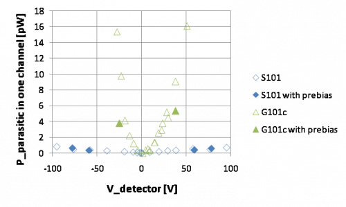
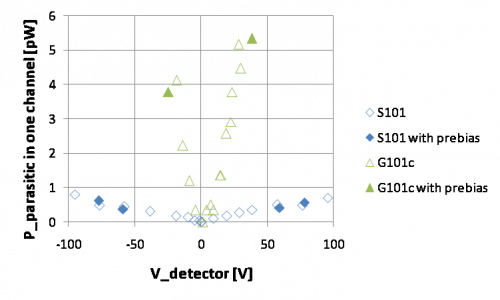
| The plots above show the results of the HV sweeps in terms of parasitic power. Left: parasitic power detected in this TES, calculated using certain assumptions from the IbIs curve. Middle: Bias power in the TES, used to calculate the first plot Right: The implied current through the detector, assuming an estimate single-channel phonon collection efficiency of 1% |
Comparing the above with the results in the last run, the parasitic power is much smaller and quite linear with detector bias, and symmetrical with HV polarity. Equivalent plots from the last run below:
| G101c (Ge HV#2) Parasitic Power versus Bias |
|---|
 |
| The plots above show the results of the HV sweeps in terms of parasitic power from Run 61, G101c (Ge HV#2). Left: parasitic power detected in this TES, calculated using certain assumptions from the IbIs curve. Middle: Bias power in the TES, used to calculate the first plot Right: The implied current through the detector, assuming an estimate single-channel phonon collection efficiency of 1% |
The parasitic power in the Ge detector was in general more than an order of magnitude worse than in the current Si detector.
  |
| 1655 | Estimate event rate by counting pulses in 20 50-ms traces. 75 pulses in 1 s = 75 Hz. |
|---|---|
| 1700 | Place 133Ba source near top of mu-metal shield. Remeasure event rate: 115 pulses in 1 s = 115 Hz. |
| 1707 | Start sequence of 14, 1-hour data series of 1-sided 0V HV Ba-source data with Frontend Gain = (20/20/5)/(6/4/3), OG = 8/4, with 1000 beginning randoms, no flashing, and a 35ADC bin threshold trigger on DCRC1 pA |
| 1710 | Tower/MC/Coldplate = 33.5/31.0/195 mK, Still = 1.25 K / 0.110 mbar, G1/G2 = 240/235 mbar, 1K Pot = 1.696 K / 30 mbar, Main bath = 60.6%. Boil off rate: a bit faster than slow mode. |
| 1749 | Fill LN2 cold trap full. |