2016/09/19 (Monday)
| DCRC1 and DCRC3 powered on and connected through HV setup EBoxDIB 2/3 → 3.2 MHz filters → Cables → remapping board I/remapping board II → HVside2board “DIB1”/“DIB2” → DCRC55(1)/50(3). Remapping boards have all possible lines switched off. . | |
| Baked using UV LEDs for 12 hours last night. Tower was at 0.55 K until 03:02 then fell to base. | |
| 0740 | Tower/MC/Coldplate = 94/61/348 mK, Still = 0.89 K / 75 μbar, G1/G2 = 130/125 mbar, 1K Pot = 1.45 K / 2.6 mbar. MB = 6.7% |
| 0745 | Fill LN2 cold trap full. Tweak 1K Pot needle valve. |
| 0750 | Start LHe transfer |
| 0820 | Stop transfer because storage Dewar is empty. MB is down to 1.4%. Get another Dewar. |
| 0840 | Restart LHe transfer at 1.4% |
| 0855 | Tower/MC/Coldplate = 85/55/313 mK, Still = 0.94 K / 110 μbar, G1/G2 = 160/155 mbar, 1K Pot = 1.59 K / 11 mbar. At the moment the 1K Pot looks pretty stable. |
| 1054 | Commence 1 minute IR bake. |
| 1103 | End LHe transfer (91.6%). (ran out of helium gas, took a while to get another cylinder. so transfer took a long time.) |
| 1116 | Release pressure from main bath. |
| 1120 | Try to fix pulse noise ringdown by attaching a 1kΩ potentiometer on the Qo feedback line of the DCRC1 switchboard. Although the pulse shape has changed with the addition of the pot, we could not adjust the pot to change the shape further. |
| DCRC1 Qo pulse 0V DCRC1/0V DCRC3 with potentiometer (post overnight IR bake) |
|---|
 |
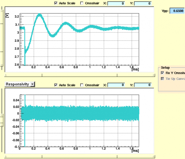
| 1130 | Try 4V HV (0V readout side) with pot connected but off, again see no change in shape of pulse, though it is good to know pulses look ok in HV. |
|---|
| DCRC1 Qo pulse 0V DCRC1/ 5V HV DCRC3 with potentiometer at 0kΩ |
|---|
 |
| 1138 | Release pressure from main bath. |
|---|---|
| 1203 | Release pressure from main bath. |
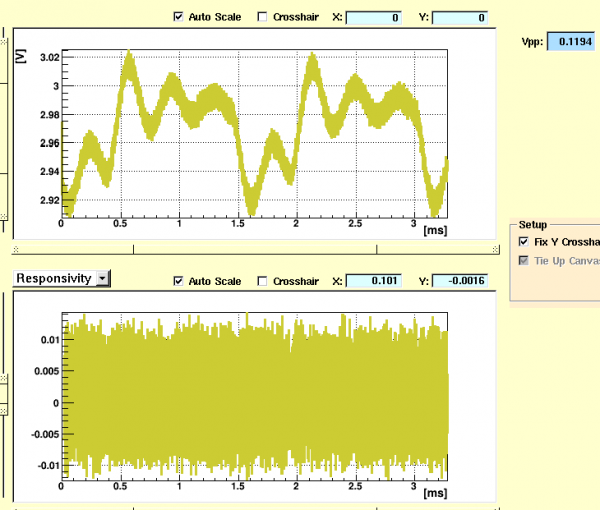
| 1240 | In attempt to reduce harmonic damped oscillator noise, introduce 1MΩ resistor on feedback line. This is done by soldering long wires onto pin 30 of DIB1 switchboard (Qouter pin), and then connecting them to a breadboard with the resistor on it, to allow for easy exchange of resistors. With 10V applied to DCRC1 (readout) usual pulses were seen before the resistor was added. Once the 1MΩ resistor was in place the pulses appeared to saturate, looking like a square wave with a 1.5 ms period. On Qinner side of DCRC1 we see odd noise, included below. Not sure why the “pulses” (or noise) are periodic, but this resistor is not what we want. |
| DCRC1 Qi ooise 10V DCRC1/0V DCRC3 1MΩ resistor |
|---|
 |
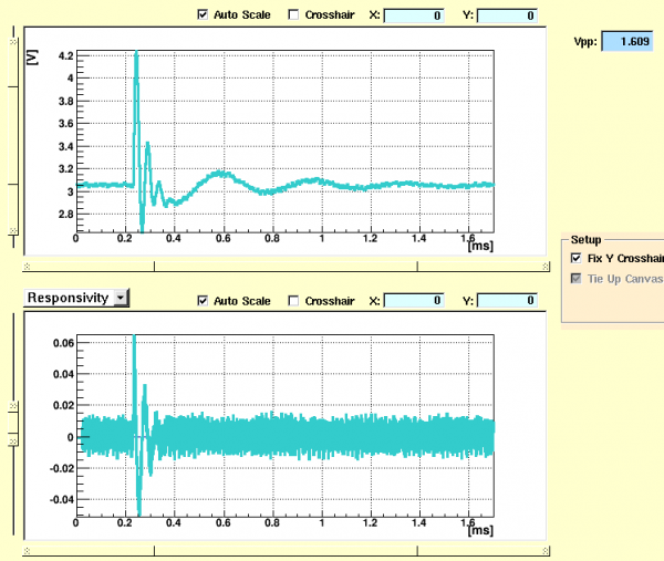
| 1250 | Try 27kΩ resistor, pulses look more like standard shape, though ringdown is still present. |
|---|
| DCRC1 Qo pulse 10V DCRC1/0V DCRC3 27kΩ resistor |
|---|
 |
| 1255 | Try 47kΩ resistor, and again pulses look similar to the 27kΩ resistor, though they overall look a but noisier/lower in amplitude. I think it needs to bake. |
|---|---|
| 1300 | Set DCRC1 Qo (readout) bias voltage to 0V, and do an IR “bake” for 10 seconds, apply 10V back on DCRC1 Qo. |
| DCRC1 Qo pulse 10V DCRC1/0V DCRC3 47kΩ resistor |
|---|
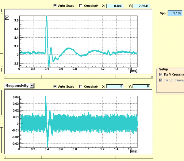 |
| 1308 | Pulse don't seem to have improved much, I don't think that bake is sufficient. |
|---|---|
| 1310 | Try 180kΩ resistor, and again seen square-looking saturated pulses. |
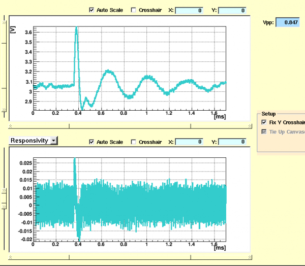
| 1312 | Try 120kΩ resistor, pulses look ok and not saturated, but the ringdown noise is very spreadout after pulse. This does not appear to be an improvement on the 27 and 47 kΩ resistors. |
| DCRC1 Qo pulse 10V DCRC1/0V DCRC3 120kΩ resistor |
|---|
 |
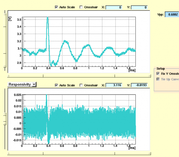
| 1320 | Try two 20 second IR flashes. Look at 120kΩ again |
|---|
| DCRC1 Qo pulse 10V DCRC1/0V DCRC3 120kΩ resistor |
|---|
 |
| 1327 | Try 150kΩ resistor, pulses saturate again. |
|---|---|
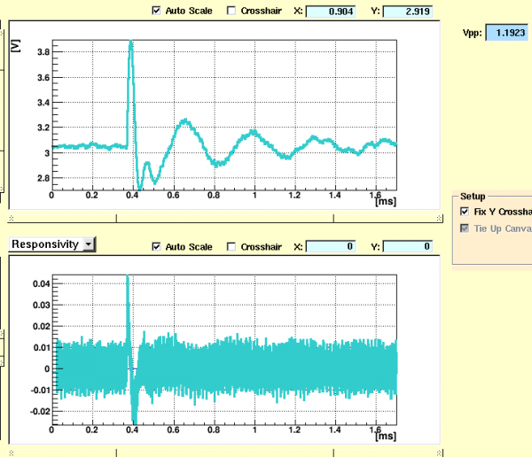
| 1329 | Try 82kΩ resistor, this also looks acceptable, but again it is slightly spread out after the initial pulse. |
| DCRC1 Qo pulse 10V DCRC1/0V DCRC3 82kΩ resistor |
|---|
 |
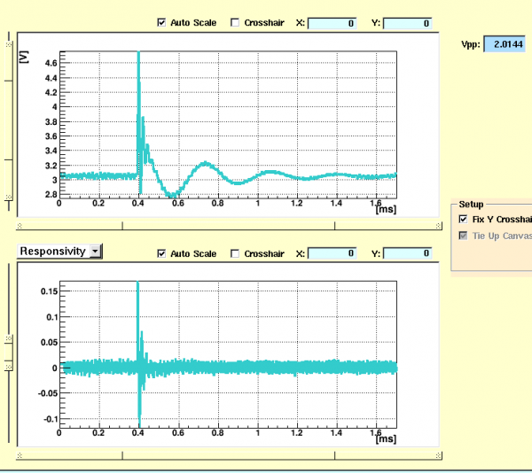
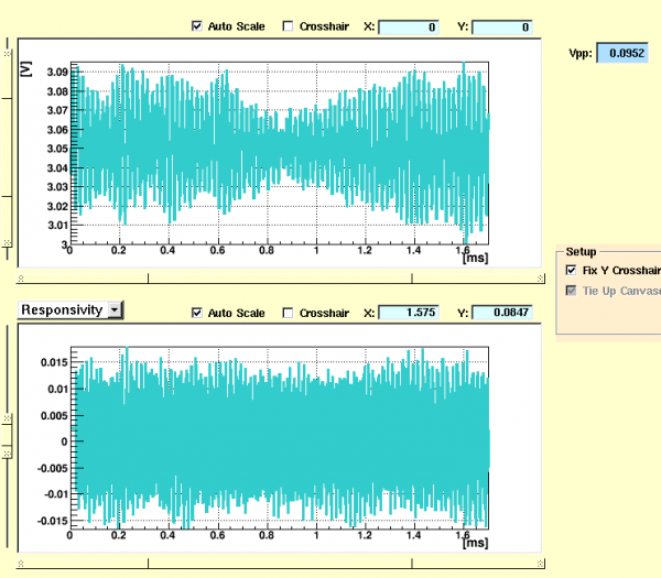
| 1330 | Try 5.8kΩ resistor, see very weird noise envelope with pulses. |
|---|
| DCRC1 Qo pulse 10V DCRC1/0V DCRC3 5.8kΩ resistor | |
|---|---|
 |  |
| 1331 | Try 6 minute IR bake. |
|---|---|
| 1337 | Just noticed HV was not grounded properly for bakes. It has been fixed. |
| 1340 | Post-bake look at 5.8kΩ resistor shows no improvement to the noise. |
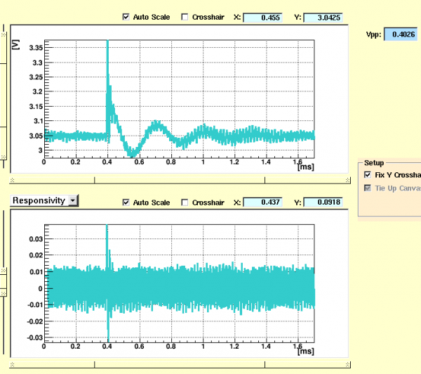
| 1345 | Try 4kΩ resistor, looks similar to 5.8kΩ resistor. Still pretty noisy. |
| DCRC1 Qo pulse 10V DCRC1/0V DCRC3 4kΩ resistor |
|---|
 |
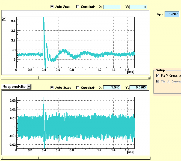
| 1350 | Try 18kΩ resistor, has a very sharp fall time. Looks good, similar to other resistors near this resistance value. |
|---|
| DCRC1 Qo pulse 10V DCRC1/0V DCRC3 18kΩ resistor |
|---|
 |
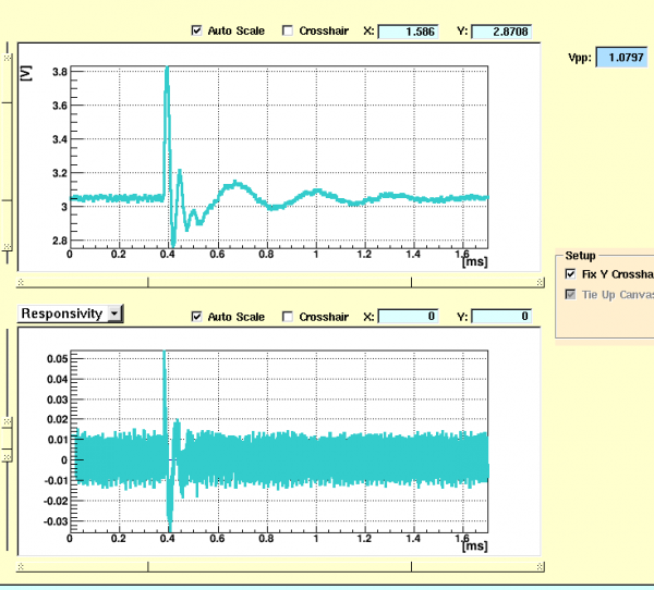
| 1355 | Try 33kΩ resistor, also looks good. Lets stick with this one for now, since we don't know what type of irregular pulse shape will make for the easiest processing, and it appears we cannot get a standard pulse shape using this resistance method and the resistors we have on hand. |
|---|
| DCRC1 Qo pulse 10V DCRC1/0V DCRC3 33kΩ resistor |
|---|
 |
| 1415 | With detector readout still at 10V Qo, turn on HV (0V), and see pulses in both shapes (negative and positive), which is pretty cool. Turn readout voltage to 0V. See 0.3 mV leakage. Turn HV up to 5V and see pulses at an increased rate (actual rate value not measured), and measure 0.9 mV leakage. |
|---|---|
| 1417 | Start 20 minute IR bake. |
| 1535 | Start taking 3 data series with a 30 second IR flash/10 minute cooldown/ 30 minute -10V DCRC1/0V DCRC3 triggering on DCRC1 Qo (threshold 7850) with 1000 initial randoms . |
| 1557 | Change charge trace length to match phonon, and then Restart taking 3 data series with a 30 second IR flash/10 minute cooldown/ 30 minute |
| 1620 | Tower/MC/Coldplate = 93/58/324 mK, Still = 0.92 K / 95 μbar, G1/G2 = 165/155 mbar, 1K Pot = 1.55 K / 5.5 mbar, MB = 88.5% 1K Pot has temperature has been pretty stable since this morning, pressure falling slowly. |
| 1625 | Tweak 1K Pot needle valve open a little more |
| 1643 | During flashing fill LN2 cold trap full. |
| 1600 | Start 20 minute UV bake (-0.8 mV). Well poo, the Qo bias was set to 0V which makes me think that when I aborted and restarted it, it had been during a time where the crystal was being flashed and thus the charge was set to 0V. Nevermind, it could also be because it was grounded in the program. We might have just taken 0V data. No way to tell until tomorrow. |
| 1634 | Although 1K pot is at 1.64 K /8 mbar, tweak needle valve just a bit to help get it though the night. |
| 1535 | Start taking 3 data series with a 30 second UV flash/10 minute cooldown/ 30 minute -10V DCRC1/0V DCRC3 triggering on DCRC1 Qo (threshold 7850) with 1000 initial randoms . |
| 2050 | Stop back in to correct possible mistake. Data taking has finished, and temperature is back to 95 mK. Switch UV back to IR, and switch to 0.6 mA on flashandflash.py program. Commence 20 minute IR back. There was an hour and fifteen minute wait between IR bake and data taking earlier, so I will wait that long for cooldown this time. If you can't tell, I am doing this from home and thus running blind. Hopefully we will have decent pulses. |
| 2207 | Start taking 3 data series with a 30 second IR flash/10 minute cooldown/ 30 minute -10V DCRC1/0V DCRC3 triggering on DCRC1 Qo (threshold 7850) with 1000 initial randoms . I hope this data looks good because I am not checking the SQUID GUI. |
| 0008 | Commence 7 hour IR bake. |