2016/08/30 (Tuesday)
| Setup: DIB1/2/3 → 3.2 MHz filters → nothing/disconnector board/remapping board → HVside2board → DCRC55(1)/50(3). Disconnector board has all charge lines disconnected. | |
| DCRCs powered overnight. Exchange gas in IVC. Mixture in Dump. | |
| 0945 | Tower temp = 297K. |
| Set up clean tent around IVC. | |
| 1015 | Overpressurize IVC with N2 gas. |
| 1030 | Begin electrical check at room temperature (differences from yesterday in bold): |
| DIB1: QIbias→QObias=13nS, QIbias→QET ret=25nS QIfb→Drain/Source <1nS, QIfb→chassis=6Ω QET ret→chassis~6nS SquidC/SquidC ret→chassis~6nS QETB→ret = 5MΩ or open Last QETB ret→chassis 2Ω (short) QiBias→chassis=6 nS and QiBias/QoBias→QET ret=25 nS |
|
| DIB2: QETB→ret=open, 89Ω, 103Ω, 90Ω QIbias/Qobias→ret=25 nS (instead of <1 nS) QIfb→Drain/Source=23/23nS, QIfb→chassis <1nS QOfb→Drain/Source=23nS, QOfb→chassis<1nS FET Tsense+→FET heater- = 0.75V (normal), QET rets→chassis ~5nS SquidA/SquidA ret→chassis=6 nS, Qibias/Qobias→chassis= 6nS |
|
| DIB3: Squid Bias D→ret (still stable) 3.1kΩ QETs/QETrets→chassis ~6nS QIfb/QOfb→chassis <1nS Bfb/Bfb ret→chassis~6nS |
| 1105 | Open IVC, keeping an eye on DIB1 shorts and other electrical issues, removing the IVC bottom and slight jiggling of DIB1 and DIB2 resulted in no noticeable change in electrical issues on DIB1 or DIB2. |
|---|---|
| 1127 | Start removing screws and heatsinks on 4K stage. Monitor for changes in electrical check. No significant change in checkout, though many of the connections to chassis (excluding QET or QET returns to chassis) were reduced from ~6nS to ~4nS. QET and QET ret to chassis to chassis are now ~5 nS. Not sure if this is significant. |
| 1143 | After unscrewing DIB2 SQUID from the tower, the shorts seen on DIB1, particularly QIfb and last QET B ret line to chassis disappeared, both now show <1nS. Jiggling or adjusting the SQUID does not bring the short back, though perhaps because we are not putting excessive tension or torque on the electronics. |
| 1148 | Remove DIB2 from tower after electrical check that reveals no change. It is then noticed that by angling the cables leading from Ebox, we are able to make the shorts from Qifb and QET B ret line to chassis appear and disappear. These shorts seem to be based on the cable, and not on the tower, which makes sense since we were taking data just fine earlier. After switching gender changers we could not make the short reappear, so that is the likely culprit, though we cannot rule out the cable itself. Using the bad gender changer with DIB2 showed QIfb to chassis to be 2Ω when we knew it to be isolated. Inspecting the gender changer showed that pin 50 (QI feedback) had been smashed. It is very possible that this gender changer has been swapped around and is responsible for some of the issues we saw with QI feedback. A quick electrical check on DIB1 with a new gender changer from the HV box(the only DIB that had used the bad gender changer since the start of the warm up) showed no issues with shorts to ground from QIfeedback or the last QET B ret line. Continue with uninstall. |
| 1342 | Remove tower. Noticed a piece of kapton tape stuck to the outside of DIB1's coax, ST-3-9 |
|---|---|
| Perform tower electrical check. Note these LEDs are connected opposite to normal. |
| Detector | G106a | DIB | 1 | |
|---|---|---|---|---|
| side coax | ST-3-9 | date/who: | 2016-08-30 | AK & NM |
| face | 1 | |||
| +lead | - lead | signal | typical | measured |
| 1 | 2 | QET A | 100 to 200 Ω | 136 Ω |
| 2 | 4 | QETA-B | 100 to 200 Ω | 218 Ω |
| 3 | 4 | QET B | 100 to 200 Ω | 203 Ω |
| 4 | 6 | QETB-C | 100 to 200 Ω | 227 Ω |
| 5 | 6 | QET C | 100 to 200 Ω | 197 Ω |
| 6 | 8 | QETC-D | 100 to 200 Ω | 209 Ω |
| 7 | 8 | QET D | 100 to 200 Ω | 162 Ω |
| 2 | 8 | QETA-D | 100 to 200 Ω | 188 Ω |
| 9 | chassis | LED1 Rforward | 8 to 9 MΩ | <1nS |
| chassis | 9 | LED1 Vforward | 1.0 to 1.1 V | 1.109 V |
| chassis | 9 | LED1 Rreverse | <1 nS | 767 kΩ |
| 10 | chassis | LED2 Rforward | 8 to 9 MΩ | <1nS |
| chassis | 10 | LED2 Vforward | 1.0 to 1.1 V | OL |
| chassis | 10 | LED2 Rreverse | <1 nS | <1 nS |
| 1 | 11 | Qo Rbias | 24 to 26 nS | 25 nS |
| 12 | 11 | Qo C coupling | <1 nS | <0.5 nS |
| 12 | 13 | Qo Rfeedback | 24 to 26 nS | 25 nS |
| 1 | 14 | Qi Rbias | 24 to 26 nS | 25 nS |
| 15 | 14 | Qi C coupling | <1 nS | <0.5 nS |
| 15 | 16 | Qi Rfeedback | 24 to 26 nS | 25 nS |
| Detector | G106a | DIB | 2 | |
|---|---|---|---|---|
| side coax | ST-3-10 | date/who: | 2016-08-30 | AK & NM |
| face | 4 | |||
| +lead | - lead | signal | typical | measured |
| 1 | 2 | QET A | 100 to 200 Ω | 213 Ω |
| 2 | 4 | QETA-B | 100 to 200 Ω | 197 Ω |
| 3 | 4 | QET B | 100 to 200 Ω | 135 Ω |
| 4 | 6 | QETB-C | 100 to 200 Ω | 196 Ω |
| 5 | 6 | QET C | 100 to 200 Ω | 181 Ω |
| 6 | 8 | QETC-D | 100 to 200 Ω | 186 Ω |
| 7 | 8 | QET D | 100 to 200 Ω | 134 Ω |
| 2 | 8 | QETA-D | 100 to 200 Ω | 207 Ω |
| 9 | chassis | LED1 Rforward | 8 to 9 MΩ | <1 nS |
| chassis | 9 | LED1 Vforward | 1.0 to 1.1 V | 1.096 V |
| chassis | 9 | LED1 Rreverse | <1 nS | 761 kΩ |
| 10 | chassis | LED2 Rforward | 8 to 9 MΩ | 3 nS |
| chassis | 10 | LED2 Vforward | 1.0 to 1.1 V | 1.095 V |
| chassis | 10 | LED2 Rreverse | <1 nS | 230 kΩ |
| 1 | 11 | Qo Rbias | 24 to 26 nS | 26 nS |
| 12 | 11 | Qo C coupling | <1 nS | <0.4 nS |
| 12 | 13 | Qo Rfeedback | 24 to 26 nS | 26 nS |
| 1 | 14 | Qi Rbias | 24 to 26 nS | 25 nS |
| 15 | 14 | Qi C coupling | <1 nS | <0.4 nS |
| 15 | 16 | Qi Rfeedback | 24 to 26 nS | 26 nS |
| Detector | G106a | DIB | 3 | |
|---|---|---|---|---|
| side coax | ST-3-3 | date/who: | 2016-08-30 | AK & NM |
| face | 5 | |||
| +lead | - lead | signal | typical | measured |
| 1 | 2 | QET A | 100 to 200 Ω | 198 Ω |
| 2 | 4 | QETA-B | 100 to 200 Ω | 240 Ω |
| 3 | 4 | QET B | 100 to 200 Ω | 219 Ω |
| 4 | 6 | QETB-C | 100 to 200 Ω | 179 Ω |
| 5 | 6 | QET C | 100 to 200 Ω | 166 Ω |
| 6 | 8 | QETC-D | 100 to 200 Ω | 175 Ω |
| 7 | 8 | QET D | 100 to 200 Ω | 150 Ω |
| 2 | 8 | QETA-D | 100 to 200 Ω | 206 Ω |
| 9 | chassis | LED1 Rforward | 8 to 9 MΩ | 8 MΩ |
| chassis | 9 | LED1 Vforward | 1.0 to 1.1 V | 1.104 V |
| chassis | 9 | LED1 Rreverse | <1 nS | 758 kΩ |
| 10 | chassis | LED2 Rforward | 8 to 9 MΩ | 490 kΩ |
| chassis | 10 | LED2 Vforward | 1.0 to 1.1 V | 1.090 V |
| chassis | 10 | LED2 Rreverse | <1 nS | 200 kΩ |
| 1 | 11 | Qo Rbias | 24 to 26 nS | <1 nS |
| 12 | 11 | Qo C coupling | <1 nS | <1 nS |
| 12 | 13 | Qo Rfeedback | 24 to 26 nS | <1 nS |
| 1 | 14 | Qi Rbias | 24 to 26 nS | <1 nS |
| 15 | 14 | Qi C coupling | <1 nS | <1 nS |
| 15 | 16 | Qi Rfeedback | 24 to 26 nS | <1 nS |
| 1405 | Tower looks good except DIB3 Rfeedback. This charge channel isn't connected, but the side coax electronics should still be good. We'll check out side coaxes to be sure. |
|---|
| Side coax | ST-3-9 | |||
|---|---|---|---|---|
| date: | 2015-06-27 | who: | DS NM | |
| +lead | - lead | signal | typical | measured |
| D11 | T11 | Qo Rbias | 25 nS | 25 nS |
| T12 | T13 | Qo Rfeedback | 25 nS | 25 nS |
| D11 | T12 | Qo C coupling | <1 nS | <1 nS |
| D12 | T14 | Qi Rbias | 25 nS | 25 nS |
| T15 | T16 | Qi Rfeedback | 25 nS | 25 nS |
| D12 | T15 | Qi C coupling | <1 nS | <1 ns |
| D(1-10) | T(1-10) | LEDs, Phonons | ? | <25Ω |
| Side coax | ST-3-10 | |||
|---|---|---|---|---|
| date: | 2015-06-27 | who: | DS NM | |
| +lead | - lead | signal | typical | measured |
| D11 | T11 | Qo Rbias | 25 nS | 27 nS |
| T12 | T13 | Qo Rfeedback | 25 nS | 26 nS |
| D11 | T12 | Qo C coupling | <1 nS | <1 nS |
| D12 | T14 | Qi Rbias | 25 nS | 25 nS |
| T15 | T16 | Qi Rfeedback | 25 nS | 26 nS |
| D12 | T15 | Qi C coupling | <1 nS | <1 ns |
| D(1-10) | T(1-10) | LEDs, Phonons | ? | <25Ω |
| Side coax | ST-3-3 | |||
|---|---|---|---|---|
| date: | 2015-06-27 | who: | DS NM | |
| +lead | - lead | signal | typical | measured |
| D11 | T11 | Qo Rbias | 27 nS | 26 nS |
| T12 | T13 | Qo Rfeedback | 25 nS | <1 nS |
| D11 | T12 | Qo C coupling | <1 nS | <1 nS |
| D12 | T14 | Qi Rbias | 25 nS | 26 nS |
| T15 | T16 | Qi Rfeedback | 25 nS | <1 nS |
| D12 | T15 | Qi C coupling | <1 nS | <1 ns |
| D(1-10) | T(1-10) | LEDs, Phonons | ? | <25Ω |
| 1444 | Side coax electrical tests confirm ST-3-3 QI,QO feedback resistors are disconnected. Visual inspection confirms broken wire bonds on Rfeeback's. However, no shorts to chassis are seen on any side coax. |
|---|
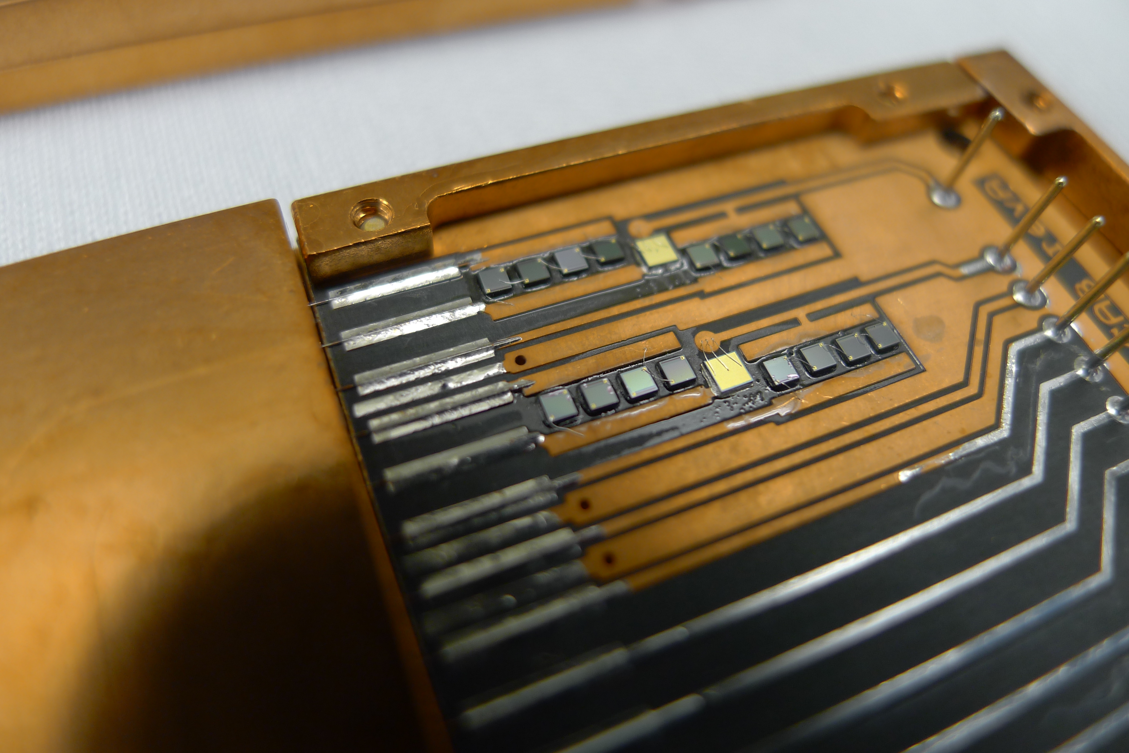
| 1517 | Perform detector check on G106a |
|---|
| Detector | G106A | DIB | 1 | |
|---|---|---|---|---|
| date/who: | 2016-08-30 | AK NM | ||
| +lead | - lead | signal | typical | measured |
| 1 | 2 | QET A | 100 to 200 Ω | 30.1 Ω |
| 3 | 4 | QET B | 100 to 200 Ω | 91.6 Ω |
| 5 | 6 | QET C | 100 to 200 Ω | 89.7 Ω |
| 7 | 8 | QET D | 100 to 200 Ω | 57.8 Ω |
| 9 | chassis | LED1 Rforward | 8 to 9 MΩ | <1 nS |
| chassis | 9 | LED1 Vforward | 1.0 to 1.1 V | 1.040 V |
| chassis | 9 | LED1 Rreverse | <1 nS | 753 kΩ |
| 10 | chassis | LED2 Rforward | 8 to 9 MΩ | <1 nS |
| chassis | 10 | LED2 Vforward | 1.0 to 1.1 V | open |
| chassis | 10 | LED2 Rreverse | <1 nS | <1nS |
| 11 | 12 | Qo-Qi | 58.0Ω | |
| 12 | 11 | Qi-Qo | 55.4Ω |
| Detector | G106A | DIB | 2 | |
|---|---|---|---|---|
| date/who: | 2016-08-30 | AK NM | ||
| +lead | - lead | signal | typical | measured |
| 1 | 2 | QET A | 100 to 200 Ω | 102.3 Ω |
| 3 | 4 | QET B | 100 to 200 Ω | 30.5 Ω |
| 5 | 6 | QET C | 100 to 200 Ω | 74.6 Ω |
| 7 | 8 | QET D | 100 to 200 Ω | 29.7 Ω |
| 9 | chassis | LED1 Rforward | 8 to 9 MΩ | <1 nS |
| chassis | 9 | LED1 Vforward | 1.0 to 1.1 V | 1.039 V |
| chassis | 9 | LED1 Rreverse | <1 nS | 750 kΩ |
| 10 | chassis | LED2 Rforward | 8 to 9 MΩ | 3 nS |
| chassis | 10 | LED2 Vforward | 1.0 to 1.1 V | 1.038 V |
| chassis | 10 | LED2 Rreverse | <1 nS | 718kΩ |
| 11 | 12 | Qo-Qi | 50.6Ω | |
| 12 | 11 | Qi-Qo | 45.5Ω |
| Detector | G106A | DIB | 3 | |
|---|---|---|---|---|
| date/who: | 2016-08-30 | AK NM | ||
| +lead | - lead | signal | typical | measured |
| 1 | 2 | QET A | 100 to 200 Ω | 94.6 Ω |
| 3 | 4 | QET B | 100 to 200 Ω | 114.0 Ω |
| 5 | 6 | QET C | 100 to 200 Ω | 66.6 Ω |
| 7 | 8 | QET D | 100 to 200 Ω | 61.9 Ω |
| 9 | chassis | LED1 Rforward | 8 to 9 MΩ | ~15MΩ |
| chassis | 9 | LED1 Vforward | 1.0 to 1.1 V | 1.040 V |
| chassis | 9 | LED1 Rreverse | <1 nS | 748 kΩ |
| 10 | chassis | LED2 Rforward | 8 to 9 MΩ | 490kΩ |
| chassis | 10 | LED2 Vforward | 1.0 to 1.1 V | 1.027 V |
| chassis | 10 | LED2 Rreverse | <1 nS | 203kΩ |
| 11 | 12 | Qo-Qi | open | |
| 12 | 11 | Qi-Qo | open |
| 1315 | Turn on He3 pump and open V9 to let mix settle in G2. |
|---|---|
| 1705 | G2 reads 783mbar. Barometric pressure = 30.13in. Correcting for barometric pressure as covered here, we get 790mbar of mixture in the dump. P2 currently reads 0.30mbar, so perhaps more can be pumped out of the fridge. Will do so tomorrow. |
| 1710 | After removing tower, 30mK can, outer 4K can, 100mK can lower half, now remove spool. Now we can remove the top part of the 4K can in order to get at the 600mK rod. |
| 2000 | Remove top portion of 4K can and remove 600 mK rod. Use copper tape to recover gaps in top portion of 4K can, and reattach 4K can. Reattach spool and kapton tape up the MC and tower thermometer (tie up with dental floss) while cleaning top flange and stripeline flange. Seal up top flange and stripeline flange (must retighten tomorrow). Reattach the stripline top buckle to keep stripelines in place. Thats it for today, bag/tape it all up to keep clean overnight. |
20:00?? -MF