2016/05/04 (Wednesday)
| Setup: HV mode, DIB1/2/3 → -/-/Phonon reroute board → cables → 3.2MHz Filters → HV board → HV1/HV2 → DCRC55/50, DCRCs powered overnight | |
| Y-Be source and Cf source near mu-metal shield at detector level for overnight activation | |
| Temperature stable overnight | |
| 0840 | Tower/MC/Coldplate = 47.3/45.5/277 mK, Still = 1.18 K / 0.110 mbar, G1/G2 = 100/100 mbar, 1K Pot = 1.64 K / 7.5 mbar, Main Bath = 15.6% |
| 0840 | Remove Y and Cf sources from fridge and return to safe |
| 0846 | Start LHe transfer @ 12.6% |
| 0900 | Fill LN cold trap bath |
| 1010 | MB level is not increasing - currently at 11.0%. This is the fourth transfer from the big Dewar. Pushed the transfer tube further into the storage Dewar, and the rate of noise from the gas meter decreased - so it must have been above liquid level, and now it's below the liquid level. |
| 0949 | Finish LHe transfer at 73.1%. |
| Emptied big Dewar. Transfer tube was pushed all the way down. 21 L left in Dewar after transfer. Used an average of 52 L per transfer for the four transfers on this Dewar, including this last partial fill. That's kinda high. | |
| 0955 | Let pressure out of MB for 30 s |
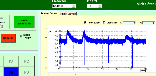
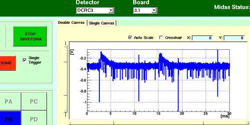
| 1030 | Getting set up for more HV tests, HV2 pB is alive again and showing pulses. Also showing very regular noise spikes in the negative direction. ~8.5ms between each one. Very regular and almost completely in the negative direction. Occasionally showing many smaller spikes in the negative direction as well, though less regular. See below: |
| HV2 pB currently showing pulses and dramatic negative spikes | |
|---|---|
 |  |
| 1100 | Commence measuring Baseline, maxVpp, and Vpp of the noise for HV2 pC and pD at various HV levels. Leakage current was not measured during these tests because no temperature spikes were observed at high HV bias which led us to wonder if measuring the leakage current could have caused the temperature spikes yesterday. We eventually found that this was not a conclusive test, as you will see below: |
|---|
| Channel | HV Bias (V) | Baseline (V) | max Vpp (mV) | Vpp Noise (mV) |
|---|---|---|---|---|
| HV pC | 0 | -0.592 | 44.7 | 1 |
| HV pD | 0 | 0.006 | 49.1 | 1 |
| HV pC | 20 | -0.581 | 38.6 | 1 |
| HV pD | 20 | 0.015 | 44.9 | 1.5 |
| HV pC | 30 | -0.551 | 20.8 | 1.5 |
| HV pD | 30 | 0.035 | 30.8 | 1.5 |
| HV pC | 35 | -0.549* | 2.3* | - |
| HV pD | 35 | 0.0495* | 9.8* | - |
| *NOTE: | After 30s the baselines and maxVpp for pC and pD had changed to -0.585 & 1.045V and 37.8 & 42.6mV, respectively. |
|||
| HV pC | 40 | -0.575 | 40.1 | 1 |
| HV pD | 40 | 1.040 | 45.9 | 1 |
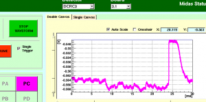
| NOTE: | After ~2min at 40V, a 5mVpp 500Hz noise appeared as seen in the below image: | |||
 |
||||
| HV pC | 45 | -0.577 | 39.1 | 1 |
| HV pD | 45 | 1.043 | 42.7 | 1 |
| HV pC | 50 | -0.578 | 38.4 | 1 |
| HV pD | 50 | 1.043 | 42.6 | 1 |
| HV pC | 55 | -0.582 | 40.7 | 1 |
| HV pD | 55 | 1.042 | 42.7 | 1 |
| HV pC | 60 | -0.584 | 29.1 | - |
| HV pD | 60 | 1.044 | 30.7 | - |
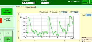
| Note: | At HV=60V, a regular 3mVpp 800Hz noise would present itself and disappear in intervals. When disappeared, the maxVpp would rise to levels seen at other HV values. After 30min, the noise would still appear in intervals. See below: |
|||
 |
||||
Observations:
- While increasing HV from 0 to 35 V, baselines of both channels increased in close to the same way, following this formula: baseline[V] = 1.9e-6*(HV[V])^2.83
- also at this same time pulses were steadily disappearing
- Then at 35 V there is a sudden change: baselines shift (pC back to where it was at 0V, pD to a very different value)
- It seems that at this point, the leakage current must have suddenly changed from the very small values of yesterday to the values seen below
- which would explain why the phonon channels were then not affected much, since the crystal bias remains low
| 1250 | After leaving the HV bias at 60V for 30min, the noise is still present, so let's risk it and measure the leakage current. Leakage current: 102.3nA and steady. No temperature spikes. This would mean that the detector is only experiencing a bias of ~15V. Damn. Time to lower the HV and record leakage currents. |
|---|
| HV (V) | Leakage Current (nA) | Calculated Bias Voltage (V) |
|---|---|---|
| 60 | 112.53 | 15.0 |
| 55 | 100.76 | 14.7 |
| 50 | 89.54 | 14.2 |
| 45 | 77.88 | 13.8 |
| 40 | 67.43 | 13.0 |
| 35 | 56.87 | 12.3 |
| 30 | 46.2 | 11.5 |
| 20 | 24.86 | 10.1 |
| 0 | -11.44 | ?? |
Formula for leakage current is 1.1*Vtest/[1 MΩ]. (The 1.1 accounts for the 10MΩ internal resistance of the multimeter. See explanation at the Run 57 summary.)
Formula for bias voltage is HV[V] - 0.4*Ileak[nA].
Observations:
- It's very strange that negative voltage at the test resistor was present when the HV was reduced to zero. (HV and Vtest are both measured by the multimeter.)
- This was repeated the next day, and again the residual negative Vtest was seen when HV was reduced to zero from a higher value. The residual current remained when the HV box was turned off, but disappeared when the HV cable was disconnected from the box. Very strange.
- The Leakage Current versus HV curve is very linear.
- If we shift the HVs down by 7V, the line passes through the origin, and the result implies a nearly constant total resistance of around 500 MΩ.
- Assuming the leakage occurs after the bias resistor, this implies a leakage resistance of only 500-400 = 100 MΩ.
- This would mean only about 20% of the HV is seen at the crystal.
- The leakage can't be going through the crystal because this would imply 1 μW power at the highest HV, totally overwhelming the phonons and probably noticeably heating the fridge.
| 1420 | Repower HV power supply and set HV to 0V. HV2 pD rails and temperature increases from 48.0mK to 49.4mK (though neither happen immediately). But now the temperature seems stable at the new temperature. |
|---|---|
| 1430 | After unrailing HV2 pB, pC, and pD by adjusting Driver Offset, raise HV slowly to 60V as an overshoot, then backpedal to 30V and measure leakage current. |
| Leakage current: 41.6nA. | |
| 1500 | After 30min, Leakage current: 41.9nA. We just cannot get this down. |
| 1515 | Lower HV to 0V, unpower HV supply and disconnect it from HV box. Flash detector for 60s. Then try again. |
| 1550 | Reconnect HV power supply (turned off) to HV box. Repower Variac and HV supply. Set HV to 30V and measure leakage current. |
| Leakage current: 42.6nA. | |
| 1610 | Leakage current still steady at 41.7nA. Flashing didn't work. Let's try unplugging the DCRCs. Lower HV to 0V. Unplug coax from side of HV board. Unpower HV power supply and Variac. Unpower DCRCs. |
| 1635 | Temperature has fallen to 46.6mK. Plug in DCRCs. Zap SQUIDs. |
| 1645 | Power on variac and HV supply. Connect coax cable to HV box. |
| 1700 | Raise HV to 30V and measure leakage current: 42.1nA. Raise HV to 60 as an overshoot, then lower back to 30V. Measure leakage current: 42.2nA. |
| 1720 | Raise HV to 100V. Leakage current: 185.9nA, which calculates out to 18.2V across the crystal. |
| 1755 | Having raised HV to 289.5V caused pulses to go away and a leakage current of 620nA. 30 minutes later, the pulses are still gone, the temperature is rising slightly, and the leakage current is still 620nA. Set HV to 0V. Unpower DCRCs. |
| 1805 | Fill LN2 cold trap full. |
| 1825 | Place Cf source and Y-88 source on mu-metal shield/source holder near detector height for overnight activation. |