| 0838 | MC/Tower = 25.2/32.0 mK, Cold plate = 139 mK, Still = 5 mW / 1.08 K / 0.19 mbar, G1/G2 = 220/210 mbar, 1K Pot = 1.70 K / 18 mbar, Main bath = 23.8% |
| 0844 | Turn off still heater. MC dips to 24.1 mK then settles back to 24.7 mK, a little lower than with the still heater on. |
| 0853 | Fill LN cold trap Dewar. |
| 1000 | Studying pulses with DCRC31-DIB1, DCRC33-DIB2, DCRCX-DIB3 configuration. See below. |
As with studies of DCRC50 yesterday and DCRC31 the day prior, we only triggered on the phonon channel of interest and we did not look beyond a front end gain of 5. Unlike RevC boards (like 31), RevC.1 boards have a front end gain of 2^x for the selected value of x up to 3 (x=4 should act like x=1 x=0), so you can select and output gain of 1, 2, 4, 8. We usually kept a trigger threshold of 250 ADC Bin for all channels. The figures below compare typical pulses from DIB3 with the three boards attached.
| Figure 1: DIB3 Phonon Channel A (BS2) Pulses |
| DCRC 31 | DCRC X | DCRC 50 |
 |  |  |
| Figure 2: DIB3 Phonon Channel B (FS2) Pulses |
| DCRC 31 | DCRC X | DCRC 50 |
 |  |  |
| Figure 3: DIB3 Phonon Channel C (ES1) Pulses |
| DCRC 31 | DCRC X | DCRC 50 |
 |  |  |
| Figure 4: DIB3 Phonon Channel D (ES2) Pulses |
| DCRC 31 | DCRC X | DCRC 50 |
 |  |  |
| Table 1: Gains and Thresholds for DCRCX in DIB3 |
| Channel | Front End Gain | Output Gain Set (Actual) | Driver Offset | Trigger Threshold |
| A | 5 | 3 (8) | +0.058 | 250 |
| B | 5 | 3 (8) | +0.030 | 250 |
| C | 5 | 3 (8) | +0.038 | 250 |
| D | 5 | 3 (8) | +0.076 | 250 |
The settings in Table 1 above, and the QET biases from Table 1 on 2015/06/09, were saved into the settings file I:\data\run053\dcrcX_dib3_0V_test.xml
We also noticed an interesting noise pattern on phonon channel C the was prevalent during pulse studies, regardless of gains applied. Two examples of this noise are included in the figures below.
| Figure 5 : DCRCX in DIB3, Phonon Channel C Odd Noise |
| Feedback Gain:5 Output Gain: 1 | Feedback Gain:5 Output Gain: 3 |
 |  |
We also included or studies on the pulse saturation level for DCRCX. In Table 2 below, see the results of this study compared to the study of DCRC50 from 2015/06/10.
| Table 2: Gains and Saturation values for DCRC50 and DCRCX in DIB3 |
| Channel | Front End Gain | Output Gain Setting/Value | DCRC50 Saturation Level (V) | DCRCX Saturation Level (V) |
| A | 1 | 1/2 | 0.22 | 0.6 |
| A | 5 | 1/2 | 0.25 | 0.8 |
| A | 5 | 2/4 | 0.50 | 0.4 |
| A | 5 | 3/8 | 1.10 | 1.3 (note: pulses were very nosy) |
| A | 5 | 4/1 | 0.10 | 0.2 |
| | | | | |
| B | 1 | 1/2 | 0.30 | 0.7 |
| B | 5 | 1/2 | 0.35 | 0.8 |
| B | 5 | 2/4 | 0.70 | 0.4 |
| B | 5 | 3/8 | 0.55 | 1.2 |
| B | 5 | 4/1 | 0.18 | 0.2 |
| | | | | |
| C | 1 | 1/2 | 0.19 | 0.7 |
| C | 5 | 1/2 | 0.19 | 0.7 |
| C | 5 | 2/4 | 0.40 | 0.35 |
| C | 5 | 3/8 | 0.80 | 1.25 |
| C | 5 | 4/1 | 0.11 | 0.2 |
| | | | | |
| D | 1 | 1/2 | 0.40 | 1.1 |
| D | 5 | 1/2 | 0.44 | 1.1 |
| D | 5 | 2/4 | 0.90 | 0.6 |
| D | 5 | 3/8 | 1.20 | 1.25 |
| D | 5 | 4/1 | 0.23 | 0.3 |
| 1110 | Commence data acquisition of DIB3 with DCRCX attached using SQUID and QET settings determined with DCRC50: -/+0 V biases; one 10-minute file; no flashing; Phonon OR charge trigger at 250 ADC bins. Store data in directory I:\data\run053\20150611. |
| 1130 | Attempts were also made to use a grounding strip to affect the pulse noise. Connecting the grounding strip from the fridge support to the Ebox yielded no change in the pulse shape. Connecting the grounding strip from the fridge support to the DCRCX back-shielding had varying results depending on the location of contact on the shield. No improvement was seen in the pulse noise, but the driver offset was shifted based on location contact, and multiple times the phonon channels were railed. However it was noted that once the other pulses had railed, phonon channel B had reduced noise. A similar test on phonon channel A showed that channel A's pulse noise was reduced when the other channels were grounded. Ungrounding phonon channel B or C (not both) did not increase channel A's pulse noise. However, ungrounding channel D (with B and C grounded) did slightly worsen channel A's pulse noise. It was also noted during this study that autwriting to board increases a channel's pulse noise. |
| 1220 | Checked vacuum jacket of transfer stick after letting it sit about 3 hours (previously it was being pumped out) : reads 0.19 mbar on the Pfeiffer gauge, along with the three bellows' volumes. Compare with the check mentioned yesterday, where after a transfer and sitting overnight it had leaked up to 1.0 mbar on the Pfeiffer. |
| 1420 | Start LHe transfer (13.2%). |
| 1500 | End LHe transfer (91.9%). |
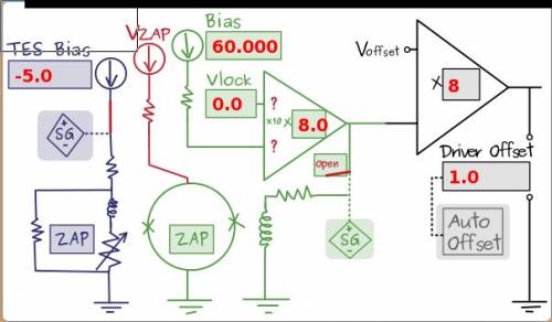
| 1630 | Return to original configuration for which the SQUID settings were found (DIB1-DCRC31, DIB2-DCRC33, DIB3-DCRC50) and attempt to alter the lockpoint to improve the noise on phonon channel D, the noisiest channel. Although altering the lockpoint did not seem to improve the noise, it was noticed that the rippled noise seen on the fall side of a pulse appears to increase with output gain at a larger rate than the baseline noise. Increasing the front end gain does not have this affect, suggesting that the ripple noise occurs after the front end gain is applied but before the output gain is applied. See the circuit diagram below for clarification where the front end gain is the value 8 applied to the green portion of the circuit, and the output gain is the value of 8 applied to the black portion of the circuit. |
| Figure 6: Phonon Circuit Diagram |
 |
| 1640 | Attempted to set up for three-DCRC running with -3.5/3.5 V bias, but ran into a noise problem: a sinusoid with a period around 1 ms, seen particularly in Qouter (forget which side, maybe both) and in all the phonon channels - it caused the base temperature to rise several mK. Tried shutting things off to get rid of it, but it seemed to disappear of its own accord after a few minutes. |
| 1700 | DIB1 pD seems to have returned! In the process of setting things up we inadvertently set SQUID settings on this previously lost channel, and saw pulses! Determined optimal setpoints and took an IbIs curve for this channel. |
| 1800 | Fill LN2 coldtrap full. |
| 1805 | Using MIDAS, set up detector flashing for 10 hours overnight. |