| 0750 | Flashing all night. MC/Tower = 93/294 mK, Cold Plate = 165 mK, Still = 1.10 K/0.13 mbar, 1K Pot = 1.72 K/19 mbar, G1/G2 = 195/192 mbar, Main bath at 77.2%. |
| 0758 | Turn off DIB1 flashing. No noticeable change in tower temperature. |
| 0800 | Turn off DIB2 flashing. Tower falls to 242 mK. |
| | Fill LN2 cold trap dewar. |
| 0803 | Turn off DIB3 flashing. Tower falls to 60 mK in 5 minutes and continues falling. |
| | Another quick cooling power run because I want to look at the cold plate temperature along with the MC and Tower temperatures: |
| 0847 | MC = 25.7 mK, tower = 32.8 mK, cold plate = 141 mK. |
| 0953 | MC set to 10 uW, Still set to 5 mW, MC = 44.5 mK, tower = 48.5 mK, cold plate = 144 mK. |
| 0953 | MC set to 30 uW, Still set to 5 mW, MC = 64.5 mK, tower = 66.0 mK, cold plate = 147 mK. |
| 0953 | MC set to 100 uW, Still set to 10 mW, MC = 104.8 mK, tower = 106 mK, cold plate = 164 mK. |
Studying the leak on the transfer tube:
Very strong leak seen squirting He through the needle into the valve, between the black grip and the red part at the end. Only seen when valve is open.
Leak checker can pump tube jacket down to 4e-3 mbar with bkg leak of 2.5 pbar*l/s
Cleaned the vacuum grease off the tube from yesterday, where the cryostat-end meets the bellows
With grease cleaned off, a short burst from the needle produced a 2X or 3X increase in the leak signal
Glopping the joint with grease again seems to get rid of the leak
Covered the end with duct tape to hold the grease in as a temporary fix.
Tried pumping out jacket then isolating it to see how well it held vacuum. With tube valve open or closed, it rises to around 1.5e-2 mbar in 10 minutes.
Used IbIs curves (tower at 34 mK, DIB1/2/3 → DCRC31/33/50) to calculate optimal QET biases (where R=Rnormal/4):
| Table 1 : QET Biases |
| dib | dchan | QET bias(μA) |
| DIB1 (DCRC31) | pA | -78 |
| DIB1 | pB | -90 |
| DIB1 | pC | -87 |
| DIB1 | pD | -73 |
| | | |
| DIB2 (DCRC33) | pA | -88 |
| DIB2 | pB | -95 |
| DIB2 | pC | -108 |
| DIB2 | pD | -82 |
| | | |
| DIB3 (DCRC50) | pA | 72 |
| DIB3 | pB | 85 |
| DIB3 | pC | 55 |
| DIB3 | pD | 89 |
| 1500 | With current DCRC configuration (31 on DIB1, 33 on DIB2, 50 on DIB3) load SQUID lockpoints from previous day and QET Biases listed above. When looking at DIB3 (DCRC 50) we noticed similar noise to the previous G106a run (see note for examples). Even when the frontend gain was increased to 50 the noise was still present. |
| 1550 | Switch DCRC configuration such that DCRC50 is on DIB1, DCRC33 is on DIB2, and DCRC31 is on DIB3. Use SQUID settings and QET biases for previous configuration. Zap all detectors. |
| 1600 | Start LHe transfer (66.1%) |
| 1626 | End LHe transfer (95.7%) |
| 1630 | Spend next couple hours studying pulses with new DCRC configuration. See below. |
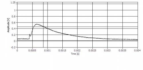
Establish timing link between boards and find that new configuration appears to have reduced pulse noise in DIB3 (now DCRC 31). However it is noted that an odd prepulse spike now appears on many of the pulses (see Figure 1 below). This spike was also seen in a study by M. Pyle et al. at Stanford. Despite this, pulses look cleaner overall on phonon channel B (first channel we studied). We easily applied the gains and trigger thresholds noted in Table 2 below (only triggering on the phonon channel of interest), and were able to see pulses such as the typical pulse shown in Figure 2. We could have increased the front end gain beyond 5, but we decided to move on and check the other channels.
| Figure 1: Prepulse Spike on Phonon Channel B |
 |
| Figure 2: DCRC 31 DIB 3: Phonon Channel B |
 |
| FrontEnd Gain of 5, Output Gain of 4, Driver Offset of -0.008, and Trigger Threshold of 50 |
Moving to phonon channel A, we found that we needed a higher trigger threshold, which we set to 250 ADC Bins. We also found that we had to continually adjust the driver offset as we increased the output gain in order to continuing triggering. As Table 2 shows, the driver offset is much higher for phonon channels A, C and D than for channel B. We also developed a routine for increasing the gain without railing/losing the pulses:
Increase the front end gain by 1, and then alter the driver offset until a pulse is visible and triggering.
Increase the front end gain again, until it reached the desired value, adjusting the driver offset after each increase. Adjust the trigger threshold as need be.
Increase the output gain in incremental values as you did with the front end gain. As before after each increase adjust the driver offset until triggering occurs.
Once both gains are at the correct values, fix the Y-axis such that you can see the pulses (or at least a portion of them) and the Y-axis zero. Adjust the driver offset until the prepulse aligns with the zero.
It was more difficult to increase the frontend and output gains and we did not attempt to increase them beyond 5 and 4, respectively.
| Figure 3: DCRC 31 DIB 3: Phonon Channel A |
 |
| FrontEnd Gain of 5, Output Gain of 4, Driver Offset of -0.048, and Trigger Threshold of 250 |
When we switched to phonon channel C, we found the odd behavior shown in Figure 4 below. However, this behavior went away once we increase the front end gain beyond 1.
| Figure 4: DCRC 31 DIB 3: Phonon Channel C Odd Behavior |
 |
| FrontEnd Gain of 1, Output Gain of 1, Driver Offset of 0.0, and Trigger Threshold of 50 |
Phonon channel C had the largest driver offset (-0.656), but the pulses still look decent (Figure 5). As with channel A, it was difficult to increase the gains, and we did not attempt to increase them beyond 5 for front end and 4 for output.
| Figure 5: DCRC 31 DIB 3: Phonon Channel C |
 |
| FrontEnd Gain of 1, Output Gain of 1, Driver Offset of -0.656, and Trigger Threshold of 250 |
Phonon channel D was the worst of the DIB3 phonon channels with this configuration, although some pulses still looks decent (as good as the pulses seen on the other channel). In Figure 6 below we included a “good” and “bad” pulse for comparison.
| Figure 6: DCRC 31 DIB 3: Phonon Channel D |
| Typical “good” pulse | Typical “bad” pulse“ |
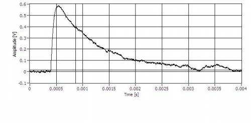 |  |
| FrontEnd Gain of 5, Output Gain of 4, Driver Offset of -0.502, and Trigger Threshold of 250 |
| Table 2: Gains and Thresholds for DCRC31 in DIB3 |
| Channel | Front End Gain | Output Gain | Driver Offset | Trigger Threshold |
| A | 5 | 4 | -0.048 | 250 |
| B | 5 | 4 | -0.008 | 50 |
| C | 5 | 4 | -0.656 | 250 |
| D | 5 | 4 | -0.502 | 250 |
The settings in Table 2 above, and the QET biases from Table 1, were saved into the settings file I:\data\run053\dcrc31_dib3_0V_test.xml
| 1710 | Fill LN2 cold trap full. |
| 1830 | Commence data acquisition of DIB3 with DCRC 33 attached using SQUID and QET settings determined with DCRC50: -/+0 V biases; one 10-minute file; accidental flashing afterwards; Phonon OR charge trigger at 250 ADC bins. Store data in directory I:\data\run053\20150609. |
| 1910 | Due to some strange heating from DCRC 50 in DIB3 DIB2 when the board was plugged in but not registering on the switch (light not coming on), we decided to power off the FETs and unplug the boards overnight. |