Table of Contents
Source Mover Paper
This paper presents the results of a motorized calibration source mover tested in UMN Run 71.
v3.3.1 NIM A Re-Submission
source_mover_v3p3p1.pdf
source_mover_reviewer_response.pdf
v3.2 NIM A Submission
source_mover_v3.2.pdf
Reviewer #2
- This paper reports on an implementation of a movable cryogenic calibration source using a superconducting stepper motor. While this is a straightforward implementation of the technology reported in reference 3, the literature on techniques of this type is sufficiently rare and novel that publication of this report is justified. However, the authors would have been well served to have followed the design reported in reference 3 more closely. The authors report a great deal of excess heating when operating their device. As the authors mention, this is likely traced to the difficulty in terminating the un-clad T48 NbTi superconducting wire used in their solenoids, and the resultant cold solder joints. A much more standard implementation, as reported in reference 3, would have been to use Cu, or CuNi clad T48 superconductor which can be properly wet with standard PbSn soft solder. Terminating un-clad NbTi wire is hard, there are methods (as mentioned in reference 3), but they involve spot welding or stripping with hydrofluoric acid and crimping. Un-clad NbTi cannot be wet with soft solder and any available flux. In addition, using Cu cladding would significantly reduce the room temperature resistance, allowing the motor to be easily tested at room temperature and in LN2 (to check for binding due to thermal contraction, without cooling below 9K). Finally, the authors report issues with fringing fields from the solenoids. It should not be hard to add a simple passive (cryoperm 10) shield around the motor to mitigate this problem.
- All of that said, I would recommend the article be published with the following minor changes:
- 1. Please estimate the power dissipated by operating the device (can use the load curve for the DR, or estimate with a heater). Is this consistent with joule heating at the wiring junction? If not, is it consistent with eddy current heating (This should scale with V^2)?
- Internal Response Notes We have only a little data to try and address this. We did some DC heating tests of the coils in R71 on 20191115 and in R72 on 20200220. These only go up to a few mA, while the motor operation needs 10s-100s of uA. These tests all produced heating, but it was consistent with a few ohms at the MC and no evidence of resistance increase like we see in motor operation. Slightly related, is that tests of the Al screw terminal indicated heating consistent with ~100 mΩ at MC for currents up to 15 mA. When operating the motor, we monitored the drive voltage and current with the o-scope, however, it seems that these are probably not reliable numbers due to how the driver board works [See Q4 ]. This hampers us in making a good guess of the current sent to the coils (though it's <750 mA/coil from the driver board). But, we also know that the motor is rated for 12 V with 122 Ohm copper windings, which indicates a max drive current of ~100 mA. We operated with a total resistance of ~120 Ohm load (with trim pot) on each line and max drive voltage of 8V, so max current of 8V/120Ω=67 mA. i.e. our estimates of operating drive current of ~40 mA may not be too far off. We can try also to go on is fridge heating with motor operation. Here, the heating was so bad, we couldn't operate the motor continuously and attain a stable fridge temp, we could only move in bursts. Our stable running mode operated for about 4 steps x 40 ms = 0.16 s, then 4 min wait, and the tower ranged between 100-750 mK. Using a fit to the cooling curve suggests 750 mK ⇒ 3.5 mW at MC (assuming MC temp ~ tower temp). Now, a drive current of ~40 mA and a joint resistance of ~1 Ohm will give P=.4^2*1 W ~ 5 mW of heating per coil. So, a joint resistance of an ohm or two at the MC can give the sort of heating we observe, given the large drive currents. Consider adding this figure (from /home/mastx027/cdms/analysis/run071/scope_trace_extract.ipynb) as evidence of coils going normal during operation
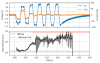
- Response to Reviewer: When operating the motor, the heating was high enough that we were unable to operate the motor and maintain a stable fridge temperature. This made accurate estimations of the heating effects of the device itself difficult. Based on the fridge temperature increase when operating the motor for a few steps, we estimate the heating power to be >3 mW. This is consistent with the Joule heating expected for the ~40 mA coil drive current and ~few Ohm resistance between the NbTi and copper wiring. We confirmed the ~few Ohm resistance by studying the fridge heating when small, DC currents were applied to one coil to provide Joule heating without actuating the motor. There may be additional significant heating due to friction and eddy currents, but we did not have stable enough operation to disentangle these effects. Additionally, we were able to indirectly monitor the coil resistance during motor operation and observe the NbTi going normal due to local heating in the motor (see attached plot). This runaway Joule heating also contributed. To address these points we have changed the 3rd paragraph of the operations section to read: “By sending low DC current (<5mA) down a single coil, we observed fridge heating consistent with a resistance of O(1 Ohm) at the location of the Nb-Ti joint and wiring harness. When driving ~35 mA through the coils to operate the motor, this O(1 mW) of heating was strong enough to drive a portion of the adjoining Nb-Ti coil normal. Once this process began, the normal portion of the Nb-Ti would also heat, leading to a runaway increase in the coil resistance and heating. By monitoring the voltage and current required to drive the motor coils, we observed such increases in resistance when operating the motor for more than ~200 us. Operating the device for much longer periods of time would overwhelm the fridge with the substantial Joule heating. This made it difficult to estimate whether friction or eddy currents caused significant additional heating.”
- 2. Add a few sentences to the final paragraph mentioning how the design could be improved:
- a. A non-square wave stepper motor controller would be really helpful, even with the “smoothing capacitors” in combating eddy current heating. Just need to use a couple of DACs and amplifiers instead of a stepper motor controller (use reference 3)
- Response to the Reviewer: That's a very good point and something we missed when looking at the current biggest problems facing us. This shouldn't be too difficult to implement into our current setup and allow for a much more optimized operating cycle. We've amended the following sentence to the conclusion: “Additional heating may have come from eddy current effects and a motor controller with a tunable waveform could improve the motor's operating cycle.”
- Notes Example circuit here
- b. Use Cu or CuNi clad NbTi wire. Also available from Supercon allowing room temperature operation (without HV) and low impedance termination of the solenoids. (use reference 3)
- Response to the Reviewer: As for the connection point itself, you are correct that a CuNi or Cu clad NB-Ti wire is the most effective way to create a low resistance joint. It turns out that we have a substantial amount of unclad Nb-Ti wire that is easier for us to use so other techniques were being explored to resolve the heating issue. Recent testing with a superconducting Al screw terminal interface seems to have reduced any heating below what the fridge can handle for a DC current test, there's no reason to believe this also shouldn't work fine for an AC current. The following has been amended to the operation section “Nb-Ti wire with no metal normally conductive cladding (e.g. Cu, CuNi, PhBr was used because it was available in the lab. However, bare Nb-Ti wire is notoriously difficult to solder and we fabricated the…” We also added the following line to the conclusion “To address the Joule heating a different connection method using superconducting Al screw terminals is being explored, but this could be entirely avoided by using Nb-Ti clad with normal conductor instead.”
- c. Add passive magnetic shielding
- Response to the Reviewer: Finally, the magnetic shielding is planned to be implemented via a Mu-Metal or Cryoperm shield between the motor and the TES surface or completely encasing the motor to contain magnetic flux. A note of this was added to the conclusion of the paper: “The inclusion of a small mu-metal shield around the motor could fix the problems associated with stray magnetic fields.”
Reviewer #3
- This paper reports on an interesting method to calibrate phonon-mediated CDMS style detectors. The detector technology uses non thermal phonons to detect particle interaction thus, a careful calibration of the detector response to event position is of utmost importance. In the field of the dark matter detection, the question of fiducial volume is very important since the experiment sensitivity scales directly with the total exposure i.e. proportion to the detector effective mass. The solution and the setup that is proposed and studied in this paper, offers a high efficiency method to study detector transient response and alleviate the requirement for multiple expensive refrigerator runs to fully characterize detectors. Considering the limited cooling power of dilution refrigerators, I am very pleased by the techniques that are used to mitigate detector volume overheating. However, I suggest a paragraph explaining the authors' estimate of various component of dissipative power including electrical Joule heating and mechanical friction in order to understand the perspective of future less dissipative devices.
- Response to Reviewer: When operating the motor, the heating was high enough that we were unable to operate the motor and maintain a stable fridge temperature. This made accurate estimations of the heating effects of the device itself difficult. Based on the fridge temperature increase when operating the motor for a few steps, we estimate the heating power to be >3 mW. This is consistent with the Joule heating expected for the ~40 mA coil drive current and ~few Ohm resistance between the NbTi and copper wiring. We confirmed the ~few Ohm resistance by studying the fridge heating when small, DC currents were applied to one coil to provide Joule heating without actuating the motor. There may be additional significant heating due to friction and eddy currents, but we did not have stable enough operation to disentangle these effects. Additionally, we were able to indirectly monitor the coil resistance during motor operation and observe the NbTi going normal due to local heating in the motor (see attached plot). This runaway Joule heating also contributed. To address these points we have changed the 3rd paragraph of the operations section to read: “By sending low DC current (<5mA) down a single coil, we observed fridge heating consistent with a resistance of O(1 Ohm) at the location of the Nb-Ti joint and wiring harness. When driving ~35 mA through the coils to operate the motor, this O(1 mW) of heating was strong enough to drive a portion of the adjoining Nb-Ti coil normal. Once this process began, the normal portion of the Nb-Ti would also heat, leading to a runaway increase in the coil resistance and heating. By monitoring the voltage and current required to drive the motor coils, we observed such increases in resistance when operating the motor for more than ~200 us. Operating the device for much longer periods of time would overwhelm the fridge with the substantial Joule heating. This made it difficult to estimate whether friction or eddy currents caused significant additional heating.”
- The authors present very well their test result using an Am-241 movable source. I found their explanation of trapped flux in the aluminum very interesting and their method of flux suppression quite intriguing. However it is not clear to me whether the thermometer that is installed on the detector cover lids can accurately indicate the true temperature of the detector specially because the detector itself is thermally isolated from the fridge. Phonon transition edge sensors can be used to indicate the true temperature of the detector. I suggest a phrase or two explaining whether the TES returns to its quiescent point (by measuring the resistance of TES) after either the mechanical motion or LED illumination will answer my question. Also I was surprised not to see any plot showing the Am-241 60 keV spectral line and whether the measured 60 keV phonon energy partition among sensors follows the same trend as that for timing.
- Response to Reviewer: It's a good point that the paper does not address why the motor operation seems to heat the aluminum fins above their 1.2 K transition temperature when the temperature spike measured by the base stage thermometer is only 500 mK. To the question of using the TES itself to measure the temperature, it should be noted that the TES part of the phonon sensor is a tungsten film with a critical temperature around 80 mK, so it has no sensitivity at these much higher temperatures. It is difficult to tell if/when the Al phonon-absorber fins are driven normal. That said, we are not overly surprised that the heating was sufficient to drive the Al normal. From critical temperature measurements, which are done by heating the base stage and then allowing it to cool (watching for the transition in both directions), we know that it takes less than a minute for the detector to come to thermal equilibrium with the base stage, but there is noticeable hysteresis suggesting a time constant in the 10s of seconds. The detector is mounted to the housing via Cirlex clamps. When the motor is hot, it can be expected to directly illuminate the Al fins with IR radiation. If this heats them above 1.2 K it's a reasonable possibility that the spike seen at the thermometer would be only 500 mK. The base plate on which the thermometer is mounted is of course well heat-sunk to the mixing chamber stage. We've added a sentence at the end of the penultimate paragraph of Section 3 explaining this: “The maximum temperature measured at the motor mounting plate was ∼500 mK, but the maximum temperature of the aluminum fins could be higher: the fins are exposed to direct IR radiation from the motor, and there is a delay of some 10s of seconds until the detector temperature comes into equilibrium with the base temperature stage through the Cirlex clamps that hold the detector in its housing.”
For this paper we chose to leave out details about the detector's position response, keeping the focus on the source mover. The pulse timing plot was added as a single example of detector response. We did also observe sensitivity to the source position in the channel energy partitions. We are continuing to study these effects and intend to publish detector position sensitivity and position reconstruction techniques in a different paper.
- Overall, I found the paper very well written and convincing with regard the solutions for a controllable mechanical motion of calibration sources in the low temperature volume of dilution refrigerators and strongly recommend publication after considering my comments above.
v3.1 arxiv v1
2002.00893.pdf
Derek
- Name Change Request, my name should be presented as D.J. Sincavage
Prisca
- First sentence in Conclusions “A simple movable source designs” get rid of the s.
v3.0
source_mover_v3.0.pdf
v3.0 Comments
Vuk
The paper is in great shape, nice work! Please see below for some comments, mostly minor. The only larger-scale issue that I can think of is that some arguments (eg about heating cause, or about the loss of PCE due to Al fins trapping flux) might appear speculative. If we are not sure of the argument, then this is the best we can do - otherwise, maybe the language could be improved a bit (see below).
- Abstract line 2, “developed as an in-situ”
- line 2: Perhaps “Semiconductor particle detectors can…” - because not every particle detector suffers from surface issues, or has bias electrodes that are mentioned later.
- line 45: The → the
- Figure 1: add a label for the source itself
- line 120-121: “may have been enough” - sounds like we are not certain that this was the cause of heating. But it seems you have observed evidence of this effect, as you state in lines 125-127, so perhaps the language here could be stronger? Eg “When driving current through the coils, Joule heating in the wiring harness and joint could be strong enough to…”
- Figure 3: includes the “+5x100mK flashes” curves and legend entry, but this is not discussed in the text. I suggest to add a sentence or two in the text to explain it, or remove it from the figure. Also, in the caption I suggest “…after motor operation (move) and restored…” (to connect better to the legend entries)
- line 183: “may have been sufficient” - again, this sounds like we are not sure if this was the cause of the PCE loss.Could we make this stronger? Maybe “was sufficient” or “was likely sufficient”?
- line 252: “way to toggle”
- general: you mention the surface vs bulk issue in the text, around the line 222. It may be interesting to add that we could also study the surface effect as a function of x-y position, because Am-241 has low energy lines that do not penetrate much into Ge. Or one could use a different source, such as a beta source. This could also be done in situ (i.e. SNOLab), because you could park the source behind a blocker.
v2.1
source_mover_v2.1.pdf
v2.1 Comments
Please include a reference to figure number or line number when adding comments. Alternatively, you can upload a pdf with inline comments.
Zach
- 165: with → within
- 167→188: The first two paragraphs of the PCE section seem to say the same thing in two different ways, and can be combined into one.
Matt
- source_mover_v2.1_fritts_comments.pdf
- Line 212, “Fig. 2”, is an example of where you should have a ~ instead of space between Fig. and the reference to make a smaller space.
Prisca
- source_mover_v2.1_prisca_comments.pdf
v1.0
source_mover_v1.0.pdf
v1.0 Comments
Please include a reference to figure number or line number when adding comments. Alternatively, you can upload a pdf with inline comments.
Matt
source_mover_elsevier-mfcomments.pdf
Derek
Comments from Derek: source_mover_v1.0_1_comments.pdf
Nick
- 37: The source holder was designed to thread onto this drive rod and rode along a square track which caused the motor rotation to linearly actuate the source position.
- 41: The drive rod thread pitch and motor step angle determined the single step actuation distance of 16.54 #mu m.
- 45: Am-241
- Reference Fig 1 somewhere early in Setup section
- 57: 13.10 mm
- 63: mechanical → electrical
- 77: source illumination
- Figure 2: grey edges show up on the left and bottom sides of the figure.
- 96: inside an Oxford
- 100 NbTi format inconsistent here and elsewhere.
- 148: at rates around → at ~
- 166: This flux in turn traps diffusing quasiparticles in the Al, reducing the fraction which heat the TES and thus lowers the observed signal. [cite Paul's thesis]
- 181: remove QET
- 186: was to operate the motor and,
- 196: and data such as this, in combination…, can be used…
- 202: Fix quotes on PAS1
- 205: delete increase
- 210: delete of
- 211: phonon sensors, allowing the …
- Figure 4: Arrival times decrease as the event is nearer a given phonon sensor.
- 216: arrival times (cite Fig 4) to the channel locations (cite Fig 2)
- 222: The effective phonon propagation speeds are observed to be a few times slower than their sound speeds in Ge. This agrees with our understanding of phonon propagation in these devices being a combination of diffusive and ballistic transport.
- 233: simple movable source designs such as this
- 244: with a secondary
- 246: delete although this will…