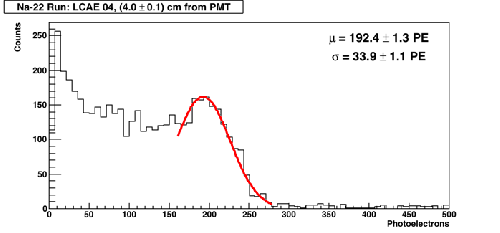
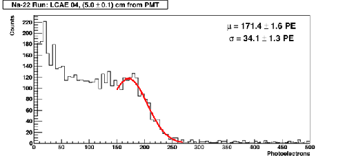
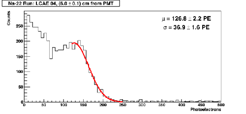
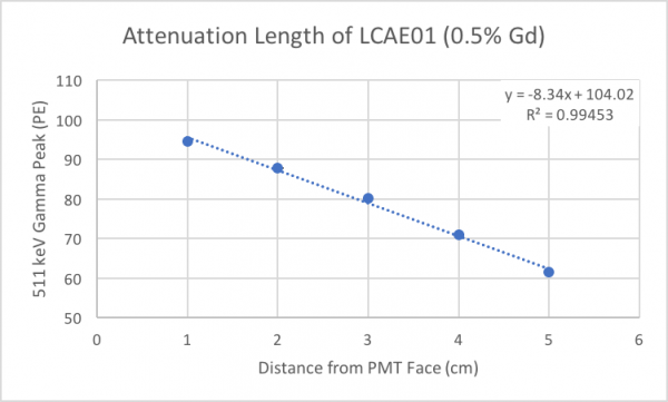
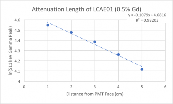
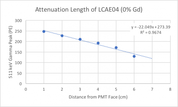
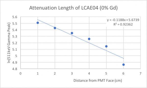
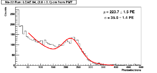
Attenuation of photons inside the sample scintillator at different points along the length of the sample was studied. An Na-22 source was used to generate back-to-back 511 keV gammas. The source was placed in a collimator, as shown in Figure 1.
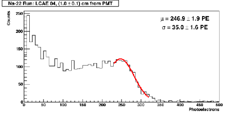
| Figure 1: Pulse Area Histogram at 1cm |
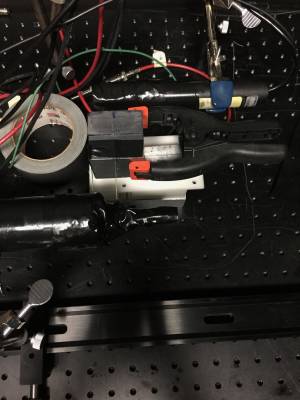 |
A PMT with a generic scintillator was positioned with its length perpendicular to the incident radiation from one face of the collimator and another PMT with the sample scintillator was positioned with its length perpendicular to the radiation from the opposite face of the collimator. The sample scintillator was wrapped with PTFE tape and a cap of black plastic was put on the face of the sample not connected to the PMT. Optical grease was applied on the other face and attached to the PMT. The sample/PMT were wrapped in aluminum foil and electrical tape.
Seven data points were collected, 1cm apart, starting from the end of the sample closest to the PMT. A bias of -2000V was applied to the PMT with the sample scintillator and a bias of -1200V was applied to the PMT (1“) with the generic scintillator.
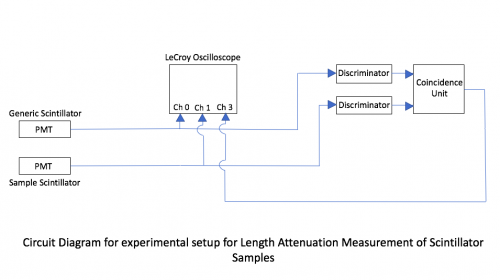
Outputs from the PMTs were connected to a Lecroy Oscilloscope and also to a discriminator. The threshold for the discriminator was set to -40mV for the two signals and a coincidence unit was used to record a coincidence between the two signals from the PMTs in a time interval of 20ns. This output from the coincidence unit was also connected to the oscilloscope. A LabView program collected data for 3000<triggers<4000.