
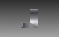
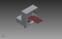
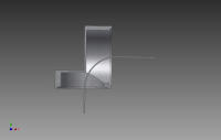
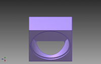
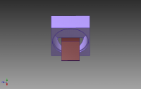
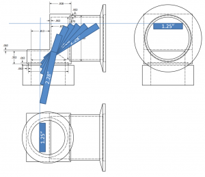
Mechanical drawing of stripline elbow
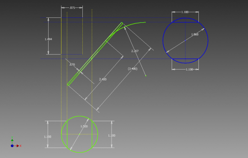
Spreadsheet with calculation of maximum connector size and necessary cable lengths
The stripline tube has a 1.444“ ID. The elbow piece presents a constraint for guiding a connector through. The planned connectors for the readout cables at both the VIB side and the tower side won't fit through the elbow and tube.
The proposed solution is to use two cables as will be used at SNOLAB. A narrow connector will join the VIB-side cable to the tower-side cable at an intermediate point. The question is whether the proposed dimensions of the intermediate connector and cable lengths will work so that the VIB-side cable will extend from VIB to IVC where it will connect to the tower-side connector which will continue to the tower connection.
The intermediate connector is proposed to be about 1.1” wide, 0.07“ thick, and 2.4” long. The elbow dimensions are such that a connector with this width and length could be as long as 3.4“ and just fit through the elbow. This gives a lot of clearance. Some extra considerations that limit the clearance are: accommodating the cable itself so that it is not overly bent during insertion; extra thickness introduced by alignment pins; and the possibility of having two cables simultaneously, so that the second connector must be inserted with the first cable present.
The tower-side cable is proposed to be 1 m long. From the IVC ceiling down along to wall and then along the floor and up to the tower connector is a total distance of about 30.2”(0.77 m). For a 1 m cable this leaves about 9“ of slack, more than enough.
The VIB-side cable is proposed to be 2 m long. The current distance from the e-box connector to the IVC ceiling is about 75.2”(1.91 m). This leaves only 3.5“ of slack. Slack is needed at both ends: at the e-box you need to be able to make the connection with the flange removed, so you need an extra several inches to do this. At the IVC ceiling you need the cable to extend far enough into the IVC to make the intermediate connection (with a fuzz-button interposer). If the e-box connection were done first and the e-box then sealed, you could perhaps pull the remaining slack into the IVC to make the intermediate connection.
But the existing e-box cannot be used because the new Vacuum Interface Board uses a different size (smaller) ISO flange. If you made an adapter between the sizes then the cable would have to be longer still, perhaps 4”. Alternatively we could build a smaller e-box. Our existing e-box is 14“ deep, certainly larger than necessary. So a smaller one would be sensible.