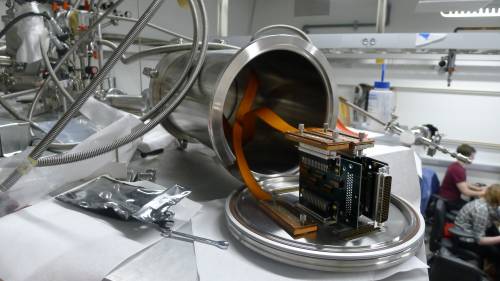
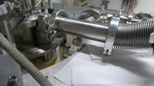
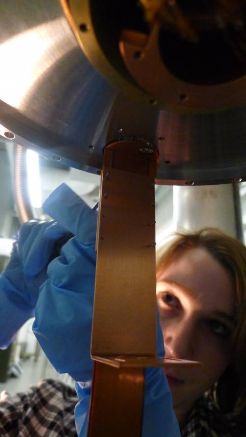
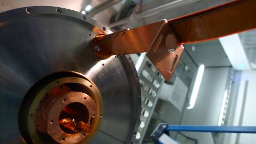
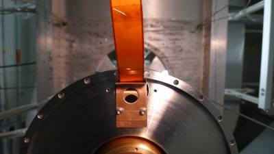
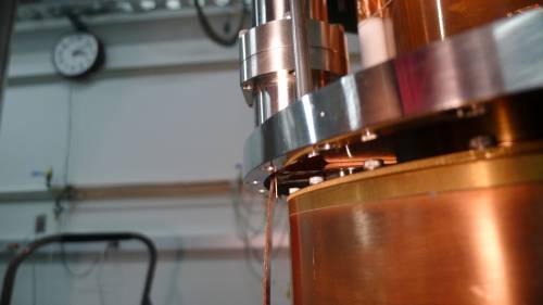
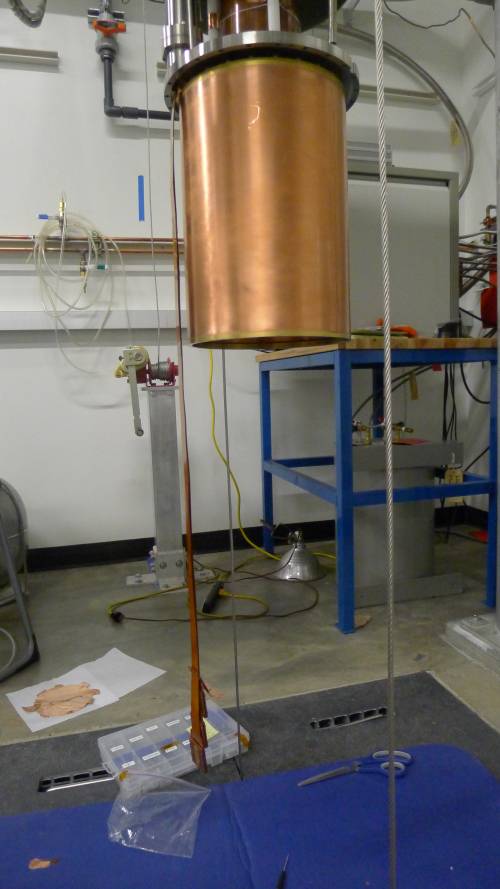
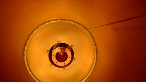
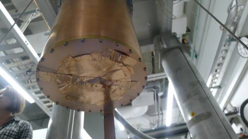
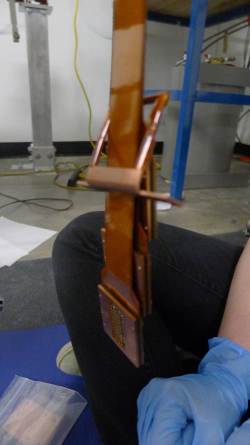
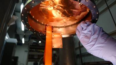
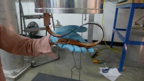
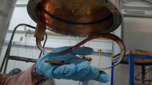
Previous prep in clean room: the cold ends of the striplines (protectors off) are fed through the elbow. Note: this fixes the rotation of the striplines relative to the elbow and thus relative to the fridge.
Previous prep in clean room: the cold ends of the striplines (protectors off) are also fed through the compression rings and o-ring that forms the top seal to the stripline tube. Screw the compression ring onto the elbow leaving just loose enough to not compress the o-ring (This time we also fed the fridge-top o-ring and compression ring onto the striplines, but this is not necessary. )
Previous prep in clean room: baffles are attached to striplines. Also protectors are reattached to cold ends. (baffle locations are important, but as of this writing I don't know what the locations are. )
Previous prep in clean room: a long piece of dental floss is tied to the bottom baffle, with a screw tied to the end. This will help to pull the striplines through the stripline tube.
Prep on fridge top: ebox and tubing through which warm ends of striplines go should be out of the way, but at the ready to lead striplines through at a later stage. The o-ring and compression ring should be put in the proper place at the fridge top. It should be screwed down to the fridge top just loose enough not to compress the o-ring. (This time we had these on the striplines.)
Note on stripline handling: they are delicate. Strong bends are to be avoided. Strong bends around hard corners should be avoided more. Twisting should be strongly avoided. All crew should wear gloves.
One person in clean room, one person in anteroom, and one person outside carry the striplines out of the clean room.
Five people is an appropriate crew size to carry out procedure.
One person is stationed on top of the fridge, with a helper partway up the ladder.
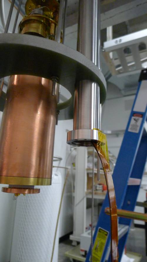
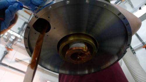
One person is beneath the fridge and guides the stripline tube up from bottom (IVC is completely removed). End of stripline tube is protected with blue painter's tape to prevent scratching it as it is guided through the baffles. Tape is removed and end of stripline tube is cleaned before gently guiding it through hole in top flange of fridge. Then it is pushed up through the lower o-ring. The person on top can tighten the compression ring to help hold the tube in place - it will need to be loosened later to move the tube through the upper o-ring. (This time we didn't have the lower o-ring there so we left it sitting in place in the upper hole.)
The cold ends are gently guided to the person atop the fridge. Other crew members are holding and protecting the rest of the length of the striplines.
The person atop the fridge must remove the protectors from the cold ends.
The person atop the fridge drops the screw with the dental floss tied to it down the stripline tube.
The person atop the fridge pushes the cold ends into the top of the stripline tube one at a time. During this procedure and the next few steps the other crew holding the striplines gently guides the striplines forward to provide slack.
The person atop the fridge pushes the baffles through one at a time. If necessary the person below pulls the dental floss to assist feeding.
When the cold ends come through the bottom the people at top and bottom can work together to feed the striplines through.
When the first baffle is close to the bottom of the tube, the elbow is guided along the striplines to the top of the fridge. (This time we also guided the fridge-top compression ring and o-ring.)
The elbow is carefully positioned above the stripline tube without harming the striplines.
The stripline tube is gently pushed up from below through the upper o-ring. At the top someone can put their finger under the striplines to make sure the tube is not pushed so far as to contact the striplines.
The striplines are at this point being held from the top. At the top of the fridge the warm ends are guided through the appropriate tubing and the tubing seals are connected in their proper places.
The warm ends are guided into the ebox. The ebox lid can be left face down at the end, and the connectors can be plugged into it (assuming the proper amount has been fed through the stripline tube.) This will hold them in place.
At this point or earlier the person at the bottom should put the protectors on the cold ends. (This is only temporary - they will be removed again.)
This is an appropriate time to take a break.
With one person on top and one or more at the bottom, disconnect the warm ends and lower the strip lines as far as can be comfortably managed. This should lower it to the bottom of the third baffle.
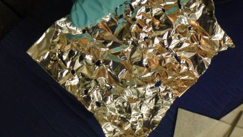
Prepare eight small pieces of aluminum foil. Poke many small holes in them to aid the flow of gas through them.
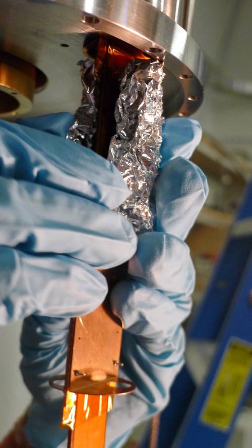
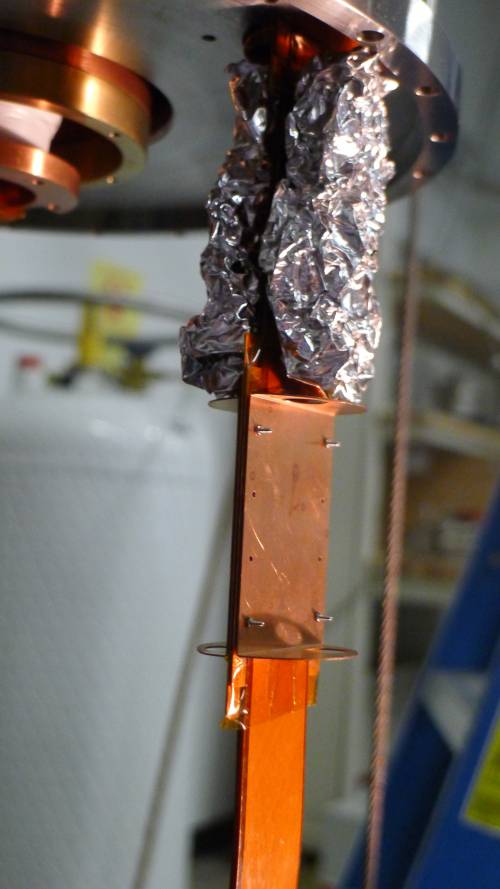
Crumple up the foil pieces and place them between the baffle disks. Make them loose enough so that they must be squished to push back up the tube, for good contact with the walls.
Add foil one section at a time, then push (and pull from top) back up the tube.
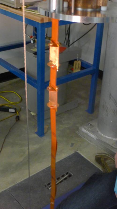
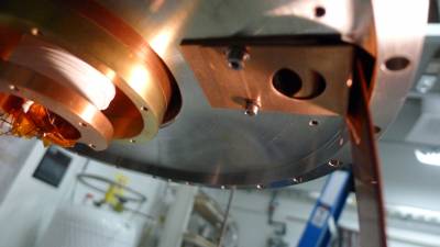
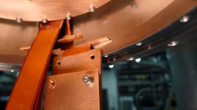
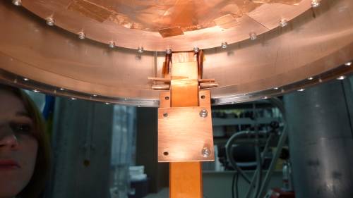
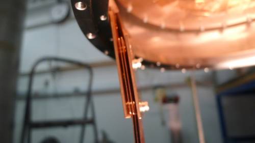
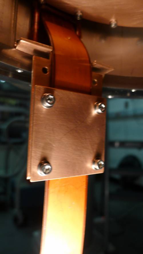
Attach the L-shaped heat sink “sandwich” to the striplines just under the lowest baffle. The foot of the L should be at the bottom and pointing toward the center of the fridge.
Push-pull the striplines up the tube so that the foot of the L is in contact with the IVC ceiling.
Place the smaller L-shaped piece on the bottom of the first one. The L-foot should point down and be oriented away from fridge center. It should push the striplines slightly outward so that they will clear the top of the 100 mK can. Striplines should hang close to outer wall of IVC.
Screw both L-shaped pieces together to IVC ceiling. Use the screws with slots cut out of them to allow pump-out of screw holes.
Cover hole in L-shaped piece with a strip of copper tape taped to the IVC ceiling. It should loosely over the hole to allow gas flow. Poke holes through it for the screw holes it covers.
Attach large lower part of 100 mK can. Make sure the striplines and tape are not in contact with it.
Attach middle part of IVC.
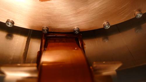
Remove protectors from IVC cold ends. Feed ends through “buckle”, so that base of buckle is at the bottom and points inward. Stripline ends should go through hole from outside in. Replace protectors.
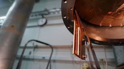
Attach lower heat-sink “sandwich” to striplines, with L-foot at top facing outward to attach to shelf at the bottom of the IVC can. It should be placed so that striplines are vertical and straight from IVC ceiling to bottom of IVC can.
Screw heat-sink and buckle together onto shelf at bottom of IVC can.