Table of Contents
Run Setup
The below setup is the same wiring as Run 80. This is done after we install the manual GHS. Run 80 has change in wiring from Run 76, 77, 78 and 79.
| Things to do: |
|---|
- The shorted line on the MotorX arm is all the way up to the Tower assembly ⇒ not related with SQUET used
- the short on the phonon lines went away after I open the IVC bottom and there were movement near the SQUETS as I unplug the motor coil wires. ⇒ possibly SQUET+diverter+stripline connection issue
Non-working channels: link Cable 2 SQUID A, Cable 1 SQUID C&D, Cable 3 SQUID C
| Run 81 Channel Map | |||||||
|---|---|---|---|---|---|---|---|
| Prev Det TwistedPair Conn refer | New Det TwistedPair Conn | Tower | Cable | DCRC(2sided) | Label | SQUID Bias, Offset | HV output, Side2-readout |
| DIB1Q (Side1pE) | DIB1Q (Side1pE) | Face5pA | Cable 2 (includes LEDs and accessories) HV CONN1 Stripline 41 ZC-70 | — | - | ||
| DIB1pB (Side1pB) | DIB3pA (Side1pF) | Face5pB | SQUID Bias= -71.8 uA, Lockpoint=-2.94 mV, | - | |||
| DIB1pA (Side1pD) | DIB4pC (Side1pA) | Face5pC | SQUID Bias= -81.1 uA, Lockpoint=-4.77 mV | - | |||
| DIB1pC (Side2pE) | | Face5pD | SQUID Bias= -88.5 uA, Lockpoint=-2.78 mV | HV2pD | |||
| DIB3pC (Side2pC) | DIB3pC (Side2pC) | Face3pA | Cable 1 HV CONN2 Stripline 48 ZC-31 | — | SQUID Bias= -58.1 uA, Lockpoint=-3.44 mV | HV2pA | |
| DIB3pB (Side2pF) | DIB3pB (Side2pF) | Face3pB | SQUID Bias= -80.1 uA, Lockpoint=-3.95 mV | HV2pB | |||
| DIB3Q (Side1pC) | DIB3Q (Side1pC) | Face3pC | - | - | |||
| DIB3pA (Side1pF) | DIB1pA (Side1pD) | Face3pD | - | - | |||
| DIB3pD (Side2pB) | | Face2pA | Cable 3 HV CONN3 Stripline 43 ZC-13 | — | SQUID Bias= -89.0 uA, Lockpoint=-5.42 mV | HV1pA | |
| DIB4pD (Side2pA) | DIB4pD (Side2pA) | Face2pB | SQUID Bias= -85.9 uA, Lockpoint=-4.13 mV | HV1pB | |||
| DIB4pC (Side1pA) | DIB1pB (Side1pB) | Face2pC | - | - | |||
| DIB1pD (Side2pD) | DIB1pD (Side2pD) | Face2pD | SQUID Bias= -88.2 uA, Lockpoint=-3.32 mV | HV1pD | |||
* Top surface of detector is Side1 (since in Run 76, it is mentioned that the source was moved towards Side1pC)
Source orientation:
- The two end-posts on the 2d source mover is along a diagonal of the hexagonal housing (one corner to opposite corner). - The move from center to parking spot will trace a U-shaped curve towards the corner of the detector. - So, to keep the source above a single channel after a move, we can keep the orientation such that the corner where the source will reach after the movement is left-side of DIB1 so that the channel is Side1pD. -Other option is to chose the horizonal rightmost-corner which will make the single channel after move to be Side1pE. the endpost in this case is along the line dividing channel E and channel C
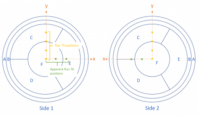
Tower Pin map:
| Pin Number | Accessory |
|---|---|
| 1 | X-endstop |
| 2 | Y-endstop |
| 3 | short to chassis |
| 4 | - |
| 5 | missing pin |
| 6 | short to chassis |
| 7 | Xarm pin4 |
| 8 | Xarm Pin3 |
| 9 | Xarm Pin2 |
| 10 | Xarm Pin1 |
| 11 | - |
| 12 | Yarm Pin1 |
| 13 | Yarm Pin2 |
| 14 | Yarm Pin3 |
| 15 | Yarm Pin4 |
| 16 | - |
Tower checks
| Run 80 Tower Electrical Checkout | |||
|---|---|---|---|
| Device | Label | Unit | Value |
| Face5pA (Cable 2) | Side1pE | Ω | 326.1 |
| Face5pB | Side1pF | Ω | 404.9 |
| Face5pC | Side1pA | Ω | 97.5 |
| Face5pD | Side2pE | Ω | 318.7 |
| Face5LED1 | pin-to-chassis | V | 1.068 |
| Face5LED2 | pin-to-chassis | V | 1.196 |
| Face3pA (Cable 1) | Side2pC | 370Ω | 375.4 |
| Face3pB | Side2pF | 507Ω | 513.6 |
| Face3pC | Side1pC | 432Ω | 436.6 |
| Face3pD | Side1pD | 398Ω | 401.9 |
| Face3pC-pD | same side inter | kΩ | 1.383 |
| Face2pA | Side2pB | 316Ω | 140.5 |
| Face2pB | Side2pA | 86Ω | 87.0 |
| Face2pC | Side1pB | 142Ω | 144.4 |
| Face2pD | Side2pD | 381Ω | 386.7 |
| Face2pA-chassis | detector shorts | Ω | |
| Face6 1-2 | Motor CoilY 1-2 | kΩ | 113 |
| Face6 3-4 | Motor CoilY 3-4 | kΩ | 112.7 |
| Face66-7 | Motor CoilX 3-4 | kΩ | 111.8 |
| Face6 8_9 | Motor CoilX 3-4 | kΩ | 110.5 |
| Face6 6-chassis | Near Endstop | kΩ | 5.685 |
| Face6 7-chassis | Far Endstop | kΩ | 22.48 |
| Face6 12-13 | Rox | kΩ | 1.072 |
Channel Mapping for HV setup
Config: DCRC3 -> HV1(L) , DCRC1 -> HV2(R)
| Config | DCRC | HV tag | Channel Name | Cable |
|---|---|---|---|---|
| 1 | DCRC3 pA | HV1 pA | Side2pE | 3pA |
| 1 | DCRC3 pB | HV1 pB | Side2pA | 3pB |
| 1 | HV1 pC | - | ||
| 1 | DCRC3 pD | HV1 pD | Side2pD | 3pD |
| 1 | DCRC1 pA | HV2 pA | Side2pC | 1pA |
| 1 | DCRC1 pB | HV2 pB | Side2pF | 1pB |
| 1 | HV2 pC | - | ||
| 1 | DCRC1 pD | HV2 pD | Side2pB | 2pD |