Table of Contents
Run Setup
The below setup is a change in wiring from Run 76, 77, 78 and 79.
| Things to do: |
|---|
- The shorted line on the MotorX arm is all the way up to the Tower assembly ⇒ not related with SQUET used
- the short on the phonon lines went away after I open the IVC bottom and there were movement near the SQUETS as I unplug the motor coil wires. ⇒ possibly SQUET+diverter+stripline connection issue
Non-working channels: link Cable 2 SQUID A, Cable 1 SQUID C&D, Cable 3 SQUID C
| Run 80 Channel Map | |||||||
|---|---|---|---|---|---|---|---|
| Prev Det TwistedPair Conn refer | New Det TwistedPair Conn | Tower | Cable | DCRC(2sided) | Label | SQUID Bias, Offset | HV output, Side2-readout |
| DIB1Q (Side1pE) | DIB1Q (Side1pE) | Face5pA | Cable 2 (includes LEDs and accessories) HV CONN1 Stripline 41 ZC-70 | — | - | ||
| DIB1pB (Side1pB) | DIB3pA (Side1pF) | Face5pB | SQUID Bias= -71.8 uA, Lockpoint=-2.94 mV, | - | |||
| DIB1pA (Side1pD) | DIB4pC (Side1pA) | Face5pC | SQUID Bias= -81.1 uA, Lockpoint=-4.77 mV | - | |||
| DIB1pC (Side2pE) | | Face5pD | SQUID Bias= -88.5 uA, Lockpoint=-2.78 mV | HV2pD | |||
| DIB3pC (Side2pC) | DIB3pC (Side2pC) | Face3pA | Cable 1 HV CONN2 Stripline 48 ZC-31 | — | SQUID Bias= -58.1 uA, Lockpoint=-3.44 mV | HV2pA | |
| DIB3pB (Side2pF) | DIB3pB (Side2pF) | Face3pB | SQUID Bias= -80.1 uA, Lockpoint=-3.95 mV | HV2pB | |||
| DIB3Q (Side1pC) | DIB3Q (Side1pC) | Face3pC | - | - | |||
| DIB3pA (Side1pF) | DIB1pA (Side1pD) | Face3pD | - | - | |||
| DIB3pD (Side2pB) | | Face2pA | Cable 3 HV CONN3 Stripline 43 ZC-13 | — | SQUID Bias= -89.0 uA, Lockpoint=-5.42 mV | HV1pA | |
| DIB4pD (Side2pA) | DIB4pD (Side2pA) | Face2pB | SQUID Bias= -85.9 uA, Lockpoint=-4.13 mV | HV1pB | |||
| DIB4pC (Side1pA) | DIB1pB (Side1pB) | Face2pC | - | - | |||
| DIB1pD (Side2pD) | DIB1pD (Side2pD) | Face2pD | SQUID Bias= -88.2 uA, Lockpoint=-3.32 mV | HV1pD | |||
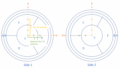
* Top surface of detector is Side1 (since in Run 76, it is mentioned that the source was moved towards Side1pC)
Source orientation:
- The two end-posts on the 2d source mover is along a diagonal of the hexagonal housing (one corner to opposite corner). - The move from center to parking spot will trace a U-shaped curve towards the corner of the detector. - So, to keep the source above a single channel after a move, we can keep the orientation such that the corner where the source will reach after the movement is left-side of DIB1 so that the channel is Side1pD. -Other option is to chose the horizonal rightmost-corner which will make the single channel after move to be Side1pE. the endpost in this case is along the line dividing channel E and channel C
Tower Pin map:
| Pin Number | Accessory |
|---|---|
| 1 | X-endstop |
| 2 | Y-endstop |
| 3 | - |
| 4 | - |
| 5 | - |
| 6 | - |
| 7 | Xarm pin4 |
| 8 | Xarm Pin3 |
| 9 | Xarm Pin2 |
| 10 | Xarm Pin1 |
| 11 | - |
| 12 | Yarm Pin1 |
| 13 | Yarm Pin2 |
| 14 | Yarm Pin3 |
| 15 | Yarm Pin4 |
| 16 | - |
Tower checks
| Run 80 Tower Electrical Checkout | |||
|---|---|---|---|
| Device | Label | Unit | Value |
| Face5pA | Side1pE | 322Ω | 326.1 |
| Face5pB | Side1pF | 135Ω | 404.9 |
| Face5pC | Side1pA | 96.8Ω | 97.5 |
| Face5pD | Side2pE | 137Ω | 318.7 |
| Face5LED1 | pin-to-chassis | V | 1.068 |
| Face5LED2 | pin-to-chassis | V | 1.196 |
| Face3pA | Side2pC | 370Ω | 375.4 |
| Face3pB | Side2pF | 507Ω | 513.6 |
| Face3pC | Side1pC | 432Ω | 436.6 |
| Face3pD | Side1pD | 398Ω | 401.9 |
| Face3pC-pD | same side inter | kΩ | 1.383 |
| Face2pA | Side2pB | 316Ω | 140.5 |
| Face2pB | Side2pA | 86Ω | 87.0 |
| Face2pC | Side1pB | 142Ω | 144.4 |
| Face2pD | Side2pD | 381Ω | 386.7 |
| Face2pA-chassis | detector shorts | Ω | |
| Face6 1-2 | Motor CoilY 1-2 | kΩ | 113 |
| Face6 3-4 | Motor CoilY 3-4 | kΩ | 112.7 |
| Face66-7 | Motor CoilX 3-4 | kΩ | 111.8 |
| Face6 8_9 | Motor CoilX 3-4 | kΩ | 110.5 |
| Face6 6-chassis | Near Endstop | kΩ | 5.685 |
| Face6 7-chassis | Far Endstop | kΩ | 22.48 |
| Face6 12-13 | Rox | kΩ | 1.072 |
Channel Mapping for HV setup
Config: DCRC3 -> HV1(L) , DCRC1 -> HV2(R)
| Config | DCRC | HV tag | Channel Name |
|---|---|---|---|
| 1 | DCRC3 pA | HV1 pA | Side2pE |
| 1 | DCRC3 pB | HV1 pB | Side2pA |
| 1 | HV1 pC | - | |
| 1 | DCRC3 pD | HV1 pD | Side2pD |
| 1 | DCRC1 pA | HV2 pA | Side2pC |
| 1 | DCRC1 pB | HV2 pB | Side2pF |
| 1 | HV2 pC | - | |
| 1 | DCRC1 pD | HV2 pD | Side2pB |